FVBE - UpCounter1by Roberto AsquiniBuild a simple 16 bit logic up counter with clear |
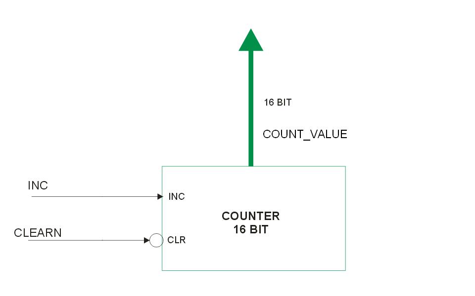
Block diagram of the UpCounter1 VHDL code
This example presents one of the simpler peripherals written in VHDL. We will show the VHDL code and the results of its simulation with the Libero suite. For a working example using this counter as a building block please refer to the Fox VHDL by Example: EventCounter1. The source code for the up counter we are presenting here is: UpCounter1.vhd.
The first lines are the declaration of the needed libraries:
library ieee;
use ieee.std_logic_1164.all;
use ieee.std_logic_unsigned.all;
library proasic3;
Then there is the entity declaration for this file that represents the interface port for this VHDL unit. Every other external block of VHDL code, to be able to use this counter, needs to declare the very same port interface as a component and needs to instantiate it.
This is the entity declaration:
entity UpCounter1 is
    port(
         COUNT_VALUE : out std_logic_vector(15 downto 0); -- 16 bit value for the actual counter.
         INC : in std_logic; -- positive edge triggered increment input line for the up counter.
         CLEARN : in std_logic -- negative logic clear input for the up counter.
                               -- It zeroes all the COUNT_VALUE lines.
    );
end UpCounter1;
In this entity we see the declaration of a 16 bit port in output: COUNT_VALUE that shows outside the module the actual counter value in any moment. The second port signal is the input INC signal that will be used here to increment the counter value. The last input port signal is the CLEARN. It will be used to reset the counter asynchronously when its logic state will be low.
Now, continuing in the file, there is the architecture declaration. The name of the architecture is Behavioral since the sequential logic working of the counter is completely declared here instead of delegating it to other inner blocks as in Structure architectures:
architecture Behavioral of UpCounter1 is

  signal counter_signals : std_logic_vector(15 downto 0); -- the actual value of the counter.

begin

  upcounter: process (CLEARN, INC)
  begin
    if (CLEARN = '0') then
      -- if CLEARN goes to zero it clears the upcounter value
      counter_signals <= (others => '0');
    elsif (INC'event and INC = '1') then
      -- if we have a positive edge front on the INC line
      -- the counter will increment
      counter_signals <= counter_signals +1;
    end if;
  end process;

  COUNT_VALUE <= counter_signals;

end Behavioral;
As you can see, the first line in the architecture, is the definition of a 16 bit internal signal that will store the actual counter value with the name counter_signals.
Then there is the definition of the single process which realizes all the counter functions. This process, as you can see just after the word process, it is sensitive only to two signals: CLEARN and INC.
@idea All the statements inside a process are executed whenever one or more of the signals present in the sensitivity list (after the word process) changes. The statements are then executed in sequential order. To have statements working in parallel (concurrency) you have to declare another process that executes in parallel with all other processes, or you have to use direct statements outside processes like the VHDL constructs WHEN or GENERATE.
The inner working of the process is simple enough now to describe. If the port signal CLEARN (coming from outside this module through the entity declaration) goes to '0' the value of counter_signal is put to zero.
@idea other => '0' is the VHDL way to have a not specified number of bits all at zero logic value so to be able to assign this word to variables of any size.
If instead the CLEARN is not '0' but we have an event on the INC port signal (also coming from outside this module) and this event is a rising front, the counter_signal will be incremented.
@idea INC'event and INC='1' means rising front of the signal INC. It is shown here a use of the attributes of the VHDL signals. INC'event will be true if an event is occurring on the signal INC. Joining this with INC='1' specifies that we want to select the rising front: "event on the signal and then the signal is '1'".
The last line is only the assignment of the internal signal counter_signals to the external port signals COUNT_VALUE, so that every change in counter_signals will be shown also on the COUNT_VALUE port signals, so exporting the counter value bits outside this module.
@ideaThis is needed for the simulation since only the root-file port signals can be made visible in a logic simulation with Libero.
Simulation of UpCounter1.vhd
In the following you can see the simulation output diagram of the UpCounter1.vhd VHDL code. This simulation has been realized using the standard tools inside the Actel suite of programs Libero 7.1:
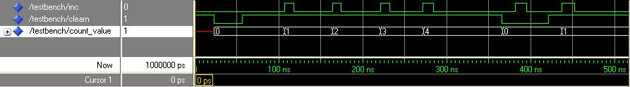
Simulation diagram of UpCounter1 VHDL code
@idea Remember that VHDL is not case sensitive! So, even if we declared the port signals in upper case, the simulator shows anyway all names in lower case.
It is possible to see that after the low state of the clearn signal, at every rising front of the inc signal the 16 bit count_value signal is incremented by 1. Then you can see that when the clearn signal is put at low logic state the count_value is zeroed and even a rising front of inc during the low state of clearn is not affecting count_value. Only after that the clearn signal is returned high the count_value will be sensitive again to the inc signal.
For a working example using this counter as a building block please refer to the Fox VHDL by Example: EventCounter1.