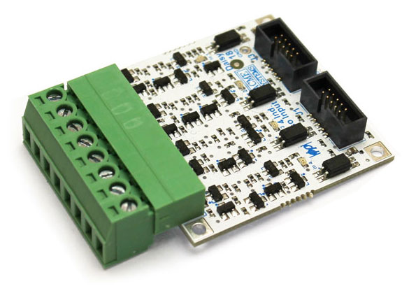
 ##Main features
* 4 input channels
* Max input voltage: 48 Volt
* Max input current:
* 15mA @ 24V
* 18mA @ 48V
* Schmitt trigger input :
* Low level input threshold: 10.5V
* High level input threshold: 16V
* Isolation voltage: 2500 Vrms (max)
The daisy connectors where to plug this board are:
| Board | Daisy Connector |
|--------|-----------------|
| FOXG20 | D2 |
| FOXG20 | D5 |
| TERRA | D11 |
| TERRA | D12 |
On the FOX Board G20 is requested a [Daisy-1](/DAISY-1) adapter.
## General Layout
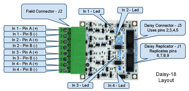
The following picture shows Daisy-18 connectors and monitoring LEDs.
##Main features
* 4 input channels
* Max input voltage: 48 Volt
* Max input current:
* 15mA @ 24V
* 18mA @ 48V
* Schmitt trigger input :
* Low level input threshold: 10.5V
* High level input threshold: 16V
* Isolation voltage: 2500 Vrms (max)
The daisy connectors where to plug this board are:
| Board | Daisy Connector |
|--------|-----------------|
| FOXG20 | D2 |
| FOXG20 | D5 |
| TERRA | D11 |
| TERRA | D12 |
On the FOX Board G20 is requested a [Daisy-1](/DAISY-1) adapter.
## General Layout
The following picture shows Daisy-18 connectors and monitoring LEDs.
 ## Connecting to a Daisy-1
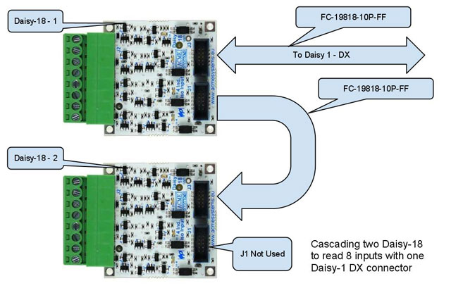
Up to 2 Daisy-18 boards can be connected to the same Daisy-1 connector by means of the Replicator connector J3. So full use of all I/O pins on a single Daisy-1 connector is made. This applies to Daisy-1 connectors: D2, D3, D5 provided all pins are set as GPIO.
Daisy-18 cascading feature is illustrated by the following picture :
## Connecting to a Daisy-1
Up to 2 Daisy-18 boards can be connected to the same Daisy-1 connector by means of the Replicator connector J3. So full use of all I/O pins on a single Daisy-1 connector is made. This applies to Daisy-1 connectors: D2, D3, D5 provided all pins are set as GPIO.
Daisy-18 cascading feature is illustrated by the following picture :
 ## Different ways to connect a Daisy-18
The "floating" optoisolated inputs of the Daisy-18 handle the following configurations
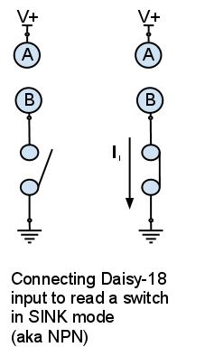
### Sink mode (aka NPN)
Up to 4 switches can be read in this configuration.
## Different ways to connect a Daisy-18
The "floating" optoisolated inputs of the Daisy-18 handle the following configurations
### Sink mode (aka NPN)
Up to 4 switches can be read in this configuration.
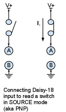
 ### Source mode (aka PNP)
Up to 4 switches can be read in this configuration.
### Source mode (aka PNP)
Up to 4 switches can be read in this configuration.
 Mixed modes are easily handled by Daisy-18 as shown in the following case list:
Case A
* Input 1 : Sink mode
* Input 2 : Sink mode
* Input 3 : Sink mode
* Input 4 : Sink mode
Case B
* Input 1 : Sink mode
* Input 2 : Sink mode
* Input 3 : Sink mode
* Input 4 : Source mode
Case C
* Input 1 : Sink mode
* Input 2 : Sink mode
* Input 3 : Source mode
* Input 4 : Source mode
Case D
* Input 1 : Sink mode
* Input 2 : Source mode
* Input 3 : Source mode
* Input 4 : Source mode
Case E
* Input 1 : Source mode
* Input 2 : Source mode
* Input 3 : Source mode
* Input 4 : Source mode
#Programming examples
Following there are some examples of code on how to use the Daisy-18 board.
Get the input state from one module:
@pg='python/daisy18/read4.py'
Get the input state from two modules wired on the same daisy connector:
@pg='python/daisy18/read8.py'
## Schematics, datasheets and related links
* [DAISY-18 Schematic](http://terzo.acmesystems.it/download/schematics/schematic_daisy18.pdf)
* [ACPL-217 Photocoupler datasheet](http://terzo.acmesystems.it/download/datasheets/ACPL-217.pdf)
* [Daisy modules and other boards available](/hqr)
@shop='DAISY-18'
@shop='FLAT-20CM'
@shop='DAISY-12'
@shop='IDC-PCB'
Mixed modes are easily handled by Daisy-18 as shown in the following case list:
Case A
* Input 1 : Sink mode
* Input 2 : Sink mode
* Input 3 : Sink mode
* Input 4 : Sink mode
Case B
* Input 1 : Sink mode
* Input 2 : Sink mode
* Input 3 : Sink mode
* Input 4 : Source mode
Case C
* Input 1 : Sink mode
* Input 2 : Sink mode
* Input 3 : Source mode
* Input 4 : Source mode
Case D
* Input 1 : Sink mode
* Input 2 : Source mode
* Input 3 : Source mode
* Input 4 : Source mode
Case E
* Input 1 : Source mode
* Input 2 : Source mode
* Input 3 : Source mode
* Input 4 : Source mode
#Programming examples
Following there are some examples of code on how to use the Daisy-18 board.
Get the input state from one module:
@pg='python/daisy18/read4.py'
Get the input state from two modules wired on the same daisy connector:
@pg='python/daisy18/read8.py'
## Schematics, datasheets and related links
* [DAISY-18 Schematic](http://terzo.acmesystems.it/download/schematics/schematic_daisy18.pdf)
* [ACPL-217 Photocoupler datasheet](http://terzo.acmesystems.it/download/datasheets/ACPL-217.pdf)
* [Daisy modules and other boards available](/hqr)
@shop='DAISY-18'
@shop='FLAT-20CM'
@shop='DAISY-12'
@shop='IDC-PCB'