|
|
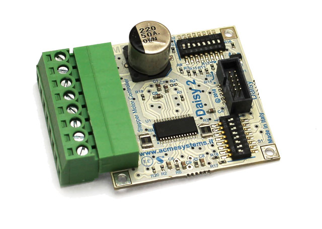
##Main features * Pulse Width Modulation (PWM) microstepping motor driver * Operating supply voltage range: 8 to 38 Volt * Current per winding: up to 2.5 A * Operating temperature tange: -40 to 85 °C * Up to 4 step modes (full step,half step,quarter step, eigth microsteps/step) selectable by dip-switch * Adjustable current (8 levels) in normal and low-power mode by dip-switch * Low-power mode selectable via GPIO line |
|
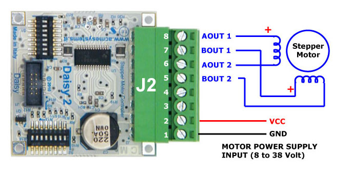
##J2 pin-out | J2 pin | IC pins | Function description | |---------|---------|----------------------| | 8 | AOUT1 | Bridge A output 1 | | 7 | BOUT1 | Bridge B output 1 | | 6 | AOUT2 | Bridge A output 2 | | 5 | BOUT2 | Bridge B output 2 | | 2,4 | VMA/VMB | Bridge A and B power supply GND | | 1,3 | GND | Bridge A and B power supply GND | |
|
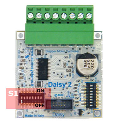
The **S1 dip-switch** selects which GPIO incoming lines link to the following DAISY-2 control
signals:
| Signal name | Signal description |
|-------------|--------------------|
| ENABLE | Logic high disables the H-Bridges, logic low enables them |
| DIR | Sets the direction of stepping |
| STEP | Rising edge causes to move one step |
| LOW POWER | Logic high level enables the low power mode |
Only four GPIO lines incoming from the CPU are used by the DAISY-2 module to control the stepper
motor.
Configuring the S1 dip-switch it is possible to select whether to use odd or even
wires available on the Daisy connector. We simply call this configurations A and B.
Configurations A and B are useful if you need to place two DAISY-7 modules on a same flat cable. Setting
A on the first board and B on the second one it is possible to control up to four DAISY-2 modules
using just D2 and D5 daisy connector.
| | 1 | 2 | 3 | 4 | 5 | 6 | 7 | 8 |
|--------|---|---|---|---|---|---|---|---|
| Configuration **A** | ON | | ON | | ON | | ON | |
| Configuration **B** | | ON | | ON | | ON | | ON |
Please be careful to use only these two dip-switch configuration to avoid shortcuts between GPIO lines.
Following are the kernel GPIO IDs used when the DAISY-2 module is plugged on **D2** or **D5** daisy
connectors on a [DAISY-1 interface](/DAISY-1).
| S1 dip # | Signal | Daisy pin | Kernel ID on D2 | Kernel ID on D5 | |-----|-------|-----------|--------------------|--| | 1 | Low-power | 8 | 57 | 84 | | 2 | Low-power | 9 | 94 | 85 | | 3 | Dir | 4 | 61 | 80 | | 4 | Dir | 5 | 60 | 81 | | 5 | Step | 6 | 59 | 82 | | 6 | Step | 7 | 58 | 83 | | 7 | Enable | 2 | 63 | 76 | | 8 | Enable | 3 | 62 | 84 | |
|
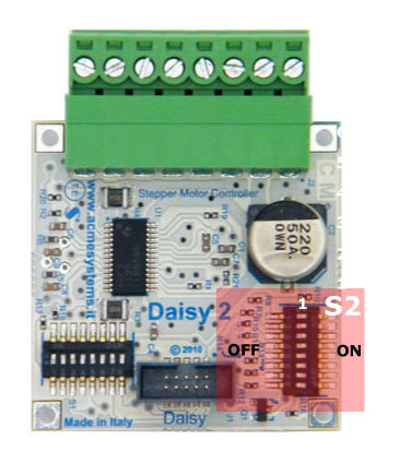
The S2 dip-switch allow you to choice the micro-stepping value and motor current for both normal and low-power mode.
Lowpower operation is a feature that can be enable via software and is useful to maintain the to motor axis in torsion
without overheat the internal coils.
USM0 and USM1 dip switch selected micro stepping mode. Refer to page # 12 on [Texas DRV8811 datasheet](http://www.ti.com/lit/ds/symlink/drv8811.pdf) for in-deep info.
| DIP 1 (USM0) | DIP 2 (USM1) | Step mode |
|--------------|--------------|-----------|
| ON | ON | Full step (2-phase excitation) |
| | ON | 1/2 step (1-2 phase excitation) |
| ON | | 1/4 step (W1-2 phase excitation) |
| | | Eight microsteps/steps |
The other dip-switches can be used to set-up the motor current and the low power condition.
| DIP 3 | DIP 4 | DIP 5 | DIP 6 | DIP 7 | DIP 8 | Ih (A)(1) | Il (A)(2) | Low power |
|-------|-------|-------|-------|-------|-------|----------|----------|--------------|
| | | | | | | 2,2 | | Disabled |
| ON | | | | | | 1,5 | | Disabled |
| | ON | | | | | 1 | | Disabled |
| ON | ON | | | | | 0,8 | | Disabled |
| | | | | ON | | 2,2 | 0,9 | Enabled |
| ON | | | ON | ON | | 1,5 | 0,7 | Enabled |
| | | ON | ON | ON | | 0,8 | 0,5 | Enabled |
| | | ON | | | ON | 2,2 | 0,2 | Enabled |
| ON | | | | ON | ON | 1,5 | 0,2 | Enabled |
| ON | ON | ON | ON | ON | ON | 0,5 | 0,1 | Enabled |
If DIP 6,7 and 8 are all OFF the low power function is disable by hardware.
(1) normal current, calculated value (2) low current, calculated value |
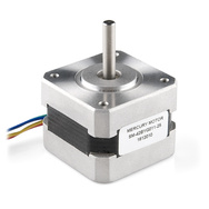 * [Product datasheet](http://www.sparkfun.com/datasheets/Robotics/SM-42BYG011-25.pdf)
* [Buy from Robot Italy](http://www.robot-italy.com/en/nema-17-stepper-motor-with-cable.html?___from_store=it)
* [Buy from Sparkfun](https://www.sparkfun.com/products/9238)
Wirings map:
| J2 pins on DAISY-2 | Mercury wire colors | Function description |
|---------|---------|----------------------|
| 1 | | GND power supply |
| 2 | | VCC (12 volt) power supply |
| 5 | BLUE | Bridge B output 2 |
| 6 | GREEN | Bridge A output 2 |
| 7 | YELLOW| Bridge B output 1 |
| 8 | RED | Bridge A output 1 |
##Wantai NMEA-23 stepper motor 57BYG621
* [Product datasheet](http://www.sparkfun.com/datasheets/Robotics/SM-42BYG011-25.pdf)
* [Buy from Robot Italy](http://www.robot-italy.com/en/nema-17-stepper-motor-with-cable.html?___from_store=it)
* [Buy from Sparkfun](https://www.sparkfun.com/products/9238)
Wirings map:
| J2 pins on DAISY-2 | Mercury wire colors | Function description |
|---------|---------|----------------------|
| 1 | | GND power supply |
| 2 | | VCC (12 volt) power supply |
| 5 | BLUE | Bridge B output 2 |
| 6 | GREEN | Bridge A output 2 |
| 7 | YELLOW| Bridge B output 1 |
| 8 | RED | Bridge A output 1 |
##Wantai NMEA-23 stepper motor 57BYG621
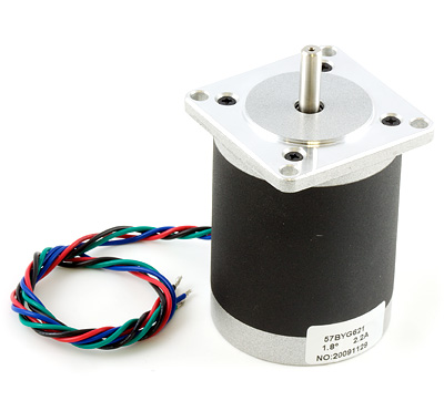 * [Product datasheet](http://www.phidgets.com/documentation/Phidgets/3307_0_Datasheet.pdf)
* [Buy from Robot Italy](http://www.robot-italy.com/it/57byg621-nema-23-bipolar-76mm-stepper.html)
* [Buy from Phidgets](http://www.phidgets.com/products.php?product_id=3307_0)
Wirings map:
| J2 pins on DAISY-2 | Wantai wire colors | Function description |
|---------|---------|----------------------|
| 1 | | GND power supply |
| 2 | | VCC (12 volt) power supply |
| 5 | BLUE | Bridge B output 2 |
| 6 | GREEN | Bridge A output 2 |
| 7 | RED | Bridge B output 1 |
| 8 | BLACK | Bridge A output 1 |
##Related links
* [Stepper motor controller IC Texas DRV8811 datasheet](http://focus.ti.com/docs/prod/folders/print/drv8811.html)
* [Mercury NEMA-17 stepper motor datasheet](http://www.sparkfun.com/datasheets/Robotics/SM-42BYG011-25.pdf)
* [Wantai NEMA-23 stepper motor datasheet](http://www.phidgets.com/documentation/Phidgets/3307_0_Datasheet.pdf)
* [Product datasheet](http://www.phidgets.com/documentation/Phidgets/3307_0_Datasheet.pdf)
* [Buy from Robot Italy](http://www.robot-italy.com/it/57byg621-nema-23-bipolar-76mm-stepper.html)
* [Buy from Phidgets](http://www.phidgets.com/products.php?product_id=3307_0)
Wirings map:
| J2 pins on DAISY-2 | Wantai wire colors | Function description |
|---------|---------|----------------------|
| 1 | | GND power supply |
| 2 | | VCC (12 volt) power supply |
| 5 | BLUE | Bridge B output 2 |
| 6 | GREEN | Bridge A output 2 |
| 7 | RED | Bridge B output 1 |
| 8 | BLACK | Bridge A output 1 |
##Related links
* [Stepper motor controller IC Texas DRV8811 datasheet](http://focus.ti.com/docs/prod/folders/print/drv8811.html)
* [Mercury NEMA-17 stepper motor datasheet](http://www.sparkfun.com/datasheets/Robotics/SM-42BYG011-25.pdf)
* [Wantai NEMA-23 stepper motor datasheet](http://www.phidgets.com/documentation/Phidgets/3307_0_Datasheet.pdf)