#DAISY-7 - GPS/MEMS module
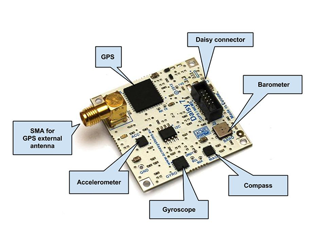
9 Degrees of Freedom module which integrated MEMS Accelerometer, Gyroscope, Compass, Barometer and GPS receiver in just 4x4cm.
 #Features
Operating Temperature range: -30 +85 deg-C
#Features
Operating Temperature range: -30 +85 deg-C
|
##GPS
* Chip Skytraq Venus638LPx
* Up to 10 reads per second
* 65 channels
* Tests 8 million time-frequency hypothesis per sec
* Open sky cold start 29 second
* Signal detection better than -161dBm
* Accuracy 2.5m [CEP](http://en.wikipedia.org/wiki/Circular_error_probable)
* ~28mA in tracking and navigation mode
* Multipath detection and suppression
* Digital output interface type: **Serial 3V3 level**
* Baudrate 115200,8,N,1 ([how to change it](/DAISY-7#gps_baudrate))
* [Datasheet in PDF format](/download/datasheets/Venus638DS_v02.pdf)
##Linear accelerometer
* Chip ST LIS331DLH
* 3-axes linear digital accelerometer
* Ultra low-power mode consumption down to 10µA
* ±2g/±4g/±8g dynamically selectable full-scale
* 16 bit data output
* Generators for free-fall and motion detection
* Sleep to wake-up function
* 6D orientation detection
* 10000g high shock survivability
* Digital output interface type: **I2C 3V3 level**
* [Datasheet in PDF format](/download/datasheets/LIS331DLH.pdf)
## Gyroscope
* Chip ST L3G4200D
* Ultra-stable three-axis
* Three selectable full scales (250/500/2000 dps)
* 16 bit-rate value data output
* 8-bit temperature data output
* Integrated low- and high-pass filters with userselectable bandwidth
* Ultra-stable over temperature and time
* Embedded power-down and sleep mode
* Embedded temperature sensor
* Embedded FIFO
* High shock survivability
* Digital output interface type: **I2C 3V3 level**
* [Datasheet in PDF format](http://terzo.acmesystems.it/download/datasheets/L3G4200D.pdf)
|
## Compass
* Chip Honeywell HMC5883L
* 3-Axis Magnetoresistive Sensors and ASIC in a 3.0x3.0x0.9mm LCC Surface Mount Package
* 12-Bit ADC Coupled with Low Noise
* AMR Sensors Achieves 5 milli-gauss
* Resolution in ±8 Gauss Fields
* Enables 1° to 2° Degree Compass Heading Accuracy
* Low Power Consumption (100µA)
* Wide Magnetic Field Range (±8Oe)
* Sensors Can Be Used in Strong Magnetic Field Environments with a 1° to 2° Degree Compass Heading Accuracy
* Fast 160 Hz Maximum Output Rate
* Digital output interface type: **I2C 3V3 level**
* [Datasheet in PDF format](http://terzo.acmesystems.it/download/datasheets/HMC5883L.pdf)
##Barometer
* Chip Bosch BMP085
* Pressure range: 300 ... 1100hPa (+9000m ... -500m above sea level)
* Low power: 5µA at 1 sample/sec. in standard mode
* Low noise:
* 0.06hPa (0.5m) in ultra low power mode
* 0.03hPa (0.25m) ultra high resolution mode
* down to 0.1m (rms noise) possible
* Digital output interface type: **I2C 3V3 level**
* [Datasheet in PDF format](http://terzo.acmesystems.it/download/datasheets/BMP085.pdf)
|
##Pinout on Daisy connector J2
| Pin # | Signal | Direction | Description |
|----|------|-----|-------------------------------------------------|
| 1 | 3V3 | | Power supply 3.3 Volt |
| 2 | TXD | I | Cpu TXD serial line wired to GPS RX line |
| 3 | RXD | O | Cpu RXD serial line wired to GPS TX line |
| 4 | NC | | Not connected |
| 5 | NC | | Not connected |
| 6 | NC | | Not connected |
| 7 | SDA | I/O | I2C Bus DATA |
| 8 | SCL | I | I2C Bus CLOCK |
| 9 | NC | | Not connected |
| 10 | GND | | Power supply GND |
The I2C bus is wired to the Compass, Accelerometer, Gyroscope and Barometer chips.
##Hardware reference
* [Schematic in pdf format](/download/schematics/schematic_daisy7.pdf)
* [Mechanical drawing in dwg format](/download/mechanicals/mechanical_daisy7.dwg)
##Wirings
These are the usable connectors where to plug this board using the factory default Linux image:
| Daisy connector | Serial device | I2C device |
|-----------------------------|----------------|------------|
| FOX Board G20 (+Daisy-1) D1 | /dev/ttyS2 | /dev/i2c-0 |
| FOX Board G20 (+Daisy-1) D6 | /dev/ttyS4 | /dev/i2c-0 |
| FOX Board G20 (+Daisy-1) D8 | /dev/ttyS3 | /dev/i2c-0 |
| TERRA D10 | /dev/ttyS4 | /dev/i2c-0 |
#Basic code examples
Following are some examples of code in Python to read the data from the chip mounted
on the DAISY-7 using a [FOX Board G20](/FOXG20) or a [Terra Board](/terra).
They use Daisy classes defined inside the the Acme Systems [ablib.py](https://github.com/tanzilli/ablib).
##Read NMEA messages from the GPS chip
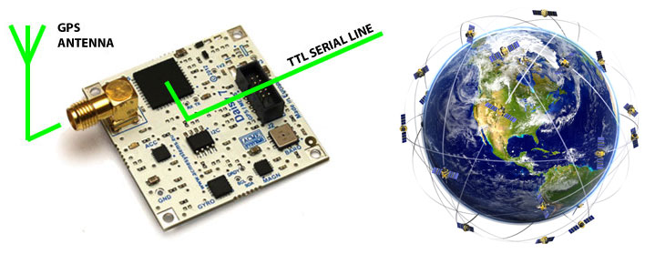
This example reads the NMEA message send by the GPS chip
on the **/dev/ttyS4** serial port (FOX.D6 or TERRA.D10 daisy connectors)
and shows them on the Linux command line.
 @pg='python/daisy7/readNMEA.py'
Run it by typing:
@pg='python/daisy7/readNMEA.py'
Run it by typing:
~/playground/python/daisy7# python readNMEA.py
$GPGGA,115609.085,4157.9279,N,01204.6836,E,1,10,0.8,20.6,M,48.9,M,,0000*6D
$GPGSA,A,3,09,12,15,29,17,25,27,04,02,14,,,1.4,0.8,1.2*3E
$GPGSV,3,1,11,12,72,325,41,09,64,115,52,27,53,121,44,25,37,272,49*7D
$GPGSV,3,2,11,14,31,308,44,02,21,117,38,04,20,078,35,29,17,205,51*78
$GPGSV,3,3,11,15,16,182,39,17,06,039,33,22,00,273,*47
$GPRMC,115609.085,A,4157.9279,N,01204.6836,E,000.0,041.6,170712,,,A*66
$GPVTG,041.6,T,,M,000.0,N,000.0,K,A*0E
$GPGGA,115610.085,4157.9279,N,01204.6836,E,1,10,0.8,20.6,M,48.9,M,,0000*65
$GPGSA,A,3,09,12,15,29,17,25,27,04,02,14,,,1.4,0.8,1.2*3E
...
##Get the GPS coordinates and show the current position on Google maps
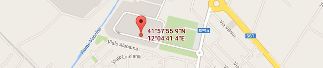
This example filters the NMEA messages **GGA - Global Positioning Systems Fix Data** and shows
the Latitute and Longitude value on the system console provideing an URL to
see on Google maps the current GPS position.
 @pg='python/daisy7/googleCoordinates.py'
Run it by typing:
@pg='python/daisy7/googleCoordinates.py'
Run it by typing:
~/playground/python/daisy7# python googleCoordinates.py
     Latitude:  41.9654233333
    Longitude:  12.07834
          URL: https://maps.google.com/maps?q=41.965423,12.078340

     Latitude:  41.9654233333
    Longitude:  12.07834
          URL: https://maps.google.com/maps?q=41.965423,12.078340

     Latitude:  41.9654233333
    Longitude:  12.07834
          URL: https://maps.google.com/maps?q=41.965423,12.078340
Insert URL value on your browser and shown where the Daisy-7 is:
* [https://maps.google.com/maps?q=41.965530,12.078173](https://maps.google.com/maps?q=41.965530,12.078173)
##Read the Accelerometer chip
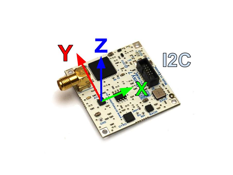
This example reads the X,Y and Z axis linear accelleration via I2C bus.
 @pg='python/daisy7/acc.py'
Run the example then move the DAISY-7 board so see linear speed variations.
@pg='python/daisy7/acc.py'
Run the example then move the DAISY-7 board so see linear speed variations.
~/playground/python/daisy7# python acc.py
X=  1216 Y=-16528 Z= -2992
X=  1200 Y=-16272 Z= -2944
X=  1136 Y=-16288 Z= -3024
X=  1184 Y=-16272 Z= -2976
X=  1184 Y=-16304 Z= -2992
X=  1168 Y=-16352 Z= -2976
##Read the Gyroscope chip
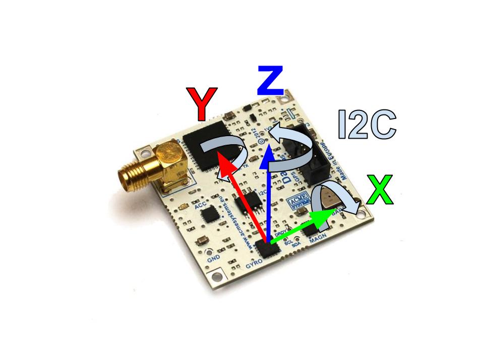
This example reads the X,Y and Z axis angular speed from the gyroscope chip via I2C bus.
 @pg='python/daisy7/gyro.py'
Run the example then move the DAISY-7 board so see angular speed variations.
@pg='python/daisy7/gyro.py'
Run the example then move the DAISY-7 board so see angular speed variations.
~/playground/python/daisy7# python gyro.py
X=   -10 Y=   -18 Z=     8
X=   -13 Y=   -17 Z=     8
X=    -2 Y=   -16 Z=     6
X=    -8 Y=   -18 Z=     7
X=    -7 Y=   -18 Z=     8
X=   -36 Y=   -18 Z=    14
##Read the Compass chip
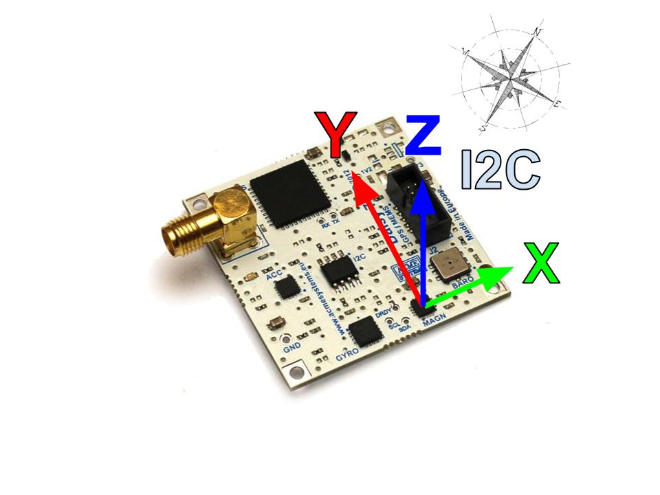 To read the Honeywell HMC5883L compass chip we have integrated
in the [ablib library](https://github.com/tanzilli/ablib) part of the [Think Bowl I2C Python Library](http://think-bowl.com/raspberry-pi/i2c-python-library-3-axis-digital-compass-hmc5883l-with-the-raspberry-pi/).
Some features of this library are:
* Easily set declination to get heading based on true north
* Heading can be retrieved in degrees and minutes or as a standard formated string for printing
* Instance can be treated as string to quickly test initial setup
* Axes can be read directly for other uses such as sensing magnets
This is an example of code to use them:
@pg='python/daisy7/compass.py'
To read the Honeywell HMC5883L compass chip we have integrated
in the [ablib library](https://github.com/tanzilli/ablib) part of the [Think Bowl I2C Python Library](http://think-bowl.com/raspberry-pi/i2c-python-library-3-axis-digital-compass-hmc5883l-with-the-raspberry-pi/).
Some features of this library are:
* Easily set declination to get heading based on true north
* Heading can be retrieved in degrees and minutes or as a standard formated string for printing
* Instance can be treated as string to quickly test initial setup
* Axes can be read directly for other uses such as sensing magnets
This is an example of code to use them:
@pg='python/daisy7/compass.py'
~/playground/python/daisy7# python compass.py
X=  -147 Y=  -184 Z=  -437
X=  -215 Y=  -314 Z=  -375
X=    57 Y=  -292 Z=  -420
X=   138 Y=  -222 Z=  -427
X=   315 Y=  -128 Z=  -353
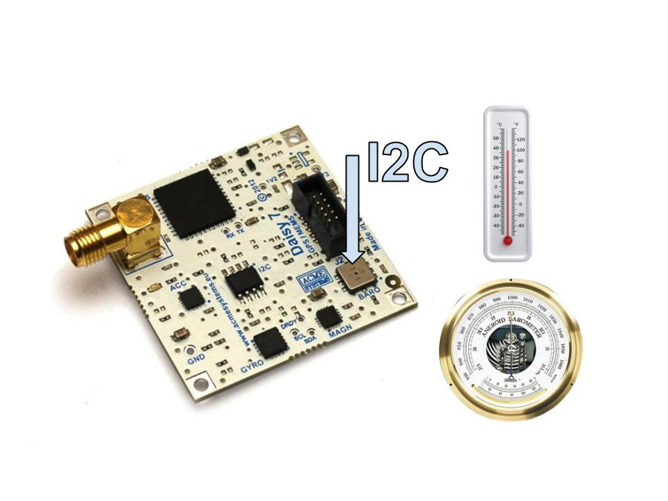
##Read the Barometer chip registers via I2C bus
 @pg='python/daisy7/baro.py'
#How to change the GPS baudrate
The serial speed of GPS chip is fixed by hardware using the pin __BAUD_SEL0__ and
__BAUD_SEL1__ visible on the schematic of GPS section. These pin are set at 3V3
via R19 and R17 resistors. R20 and R18 are Not Mounted.
@pg='python/daisy7/baro.py'
#How to change the GPS baudrate
The serial speed of GPS chip is fixed by hardware using the pin __BAUD_SEL0__ and
__BAUD_SEL1__ visible on the schematic of GPS section. These pin are set at 3V3
via R19 and R17 resistors. R20 and R18 are Not Mounted.
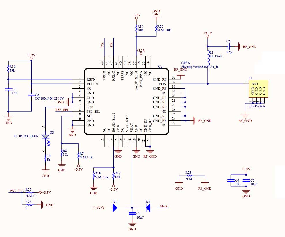 This is the table of the serial speeds we can set changing the state of these pins:
| Speed | BAUD_SEL0 | BAUD_SEL1 | R17 | R18 | R19 | R20 |
|----------|-----------|-----------|-----|-----|-----|-----|
| 4800 | 1 | 0 | No | Yes | Yes | No |
| 9600 | 0 | 0 | No | Yes | No | Yes |
| 38400 | 0 | 1 | Yes | No | No | Yes |
| 115200 | 1 | 1 | Yes | No | Yes | No |
#Buy
@shop='DAISY-7'
@shop='GPSANT'
@shop='FLAT-20CM'
@shop='DAISY-12'
@shop='IDC-PCB'
This is the table of the serial speeds we can set changing the state of these pins:
| Speed | BAUD_SEL0 | BAUD_SEL1 | R17 | R18 | R19 | R20 |
|----------|-----------|-----------|-----|-----|-----|-----|
| 4800 | 1 | 0 | No | Yes | Yes | No |
| 9600 | 0 | 0 | No | Yes | No | Yes |
| 38400 | 0 | 1 | Yes | No | No | Yes |
| 115200 | 1 | 1 | Yes | No | Yes | No |
#Buy
@shop='DAISY-7'
@shop='GPSANT'
@shop='FLAT-20CM'
@shop='DAISY-12'
@shop='IDC-PCB'