#GSM/SMS remote control application with BEE Board
This article illustrates some basic ideas for how to build remote control applications using SMS or simple toll free GSM calls
using the [BEE Board](/BEEBOARD) and some [Daisy modules](/index_daisy).
The key module to implement these applications is the [DAISY-13](/DAISY-13) which contains a quad band GSM modem, a SIM holder and a GSM antenna and talks with the BEE Board through a software serial port on the W4 connector.
This module extends the BEE Board capabilities to:
* Receive and transmit SMS
* Make and receive rings over GSM network
* Manages the SIM phonebook
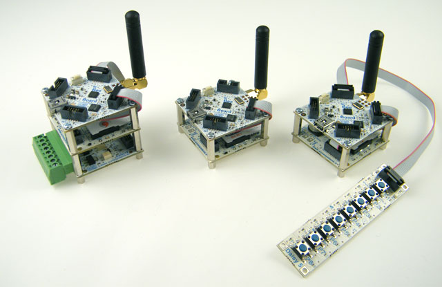 #Application examples
All the application examples listed below are fully working and can be made with a basic kit called [BEEKIT-2](/BEEKIT-2) and
one or more other [Daisy interfaces](/index_daisy). The code provided is fully open source and can be integrated into your own applications under
GPL licence terms.
##Toll free remote control via GSM
This application receives a telephone call, checks if the incoming number is stored on the SIM card phonebook, if yes turns on a relay for 1 second
then hangs up on the incoming call. Because there is no need to answer the call but only check caller ID, there is no charge for the caller.
#Application examples
All the application examples listed below are fully working and can be made with a basic kit called [BEEKIT-2](/BEEKIT-2) and
one or more other [Daisy interfaces](/index_daisy). The code provided is fully open source and can be integrated into your own applications under
GPL licence terms.
##Toll free remote control via GSM
This application receives a telephone call, checks if the incoming number is stored on the SIM card phonebook, if yes turns on a relay for 1 second
then hangs up on the incoming call. Because there is no need to answer the call but only check caller ID, there is no charge for the caller.
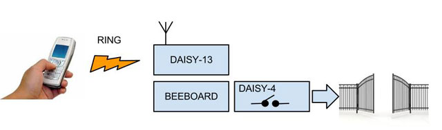 The main field application of this example could be a remote controller to open a gate used by more than one person.
In this way it's possible to save the cost of one radio controller per person by just adding the mobile
phone number of those who are enabled to ring and open the gate.
The hardware required is:
* a [BEEKIT-2](/BEEKIT-2)
* a [DAISY-4](/DAISY-4) relay module
* a daisy flat cable
* a GSM SIM card
Code for Arduino IDE 23 or less TollFreeRelay.pde
Code for Arduino IDE 1.0 or greater TollFreeRelay.ino
##Remote control via SMS
This examples illustrates how to make a SMS remote control to set up to 4 output line.
The main field application of this example could be a remote controller to open a gate used by more than one person.
In this way it's possible to save the cost of one radio controller per person by just adding the mobile
phone number of those who are enabled to ring and open the gate.
The hardware required is:
* a [BEEKIT-2](/BEEKIT-2)
* a [DAISY-4](/DAISY-4) relay module
* a daisy flat cable
* a GSM SIM card
Code for Arduino IDE 23 or less TollFreeRelay.pde
Code for Arduino IDE 1.0 or greater TollFreeRelay.ino
##Remote control via SMS
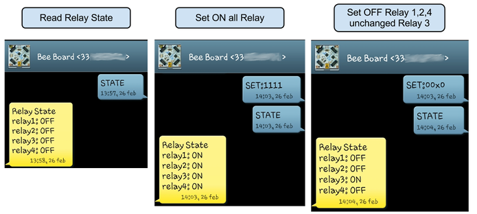
This examples illustrates how to make a SMS remote control to set up to 4 output line.
 The hardware required is:
* a [BEEKIT-2](/BEEKIT-2)
* a [DAISY-19](/DAISY-19) 4 channel output line module
Code for Arduino IDE 23 or less SMS4Relay.pde
Code for Arduino IDE 1.0 or greater SMS4Relay.ino
##Short message shooter
Build a push button panel that shoots an SMS to different mobile number with different message text.
The hardware required is:
* a [BEEKIT-2](/BEEKIT-2)
* a [DAISY-5](/DAISY-5) 8 push-button module
Code for Arduino IDE 23 or less SMSshooter.pde
Code for Arduino IDE 1.0 or greater SMSshooter.ino
#Setup
##Install the DAISY-13 BEE Board Library
* Close Arduino IDE.
* Clone BeeGSM libraries from our git repository.
The hardware required is:
* a [BEEKIT-2](/BEEKIT-2)
* a [DAISY-19](/DAISY-19) 4 channel output line module
Code for Arduino IDE 23 or less SMS4Relay.pde
Code for Arduino IDE 1.0 or greater SMS4Relay.ino
##Short message shooter
Build a push button panel that shoots an SMS to different mobile number with different message text.
The hardware required is:
* a [BEEKIT-2](/BEEKIT-2)
* a [DAISY-5](/DAISY-5) 8 push-button module
Code for Arduino IDE 23 or less SMSshooter.pde
Code for Arduino IDE 1.0 or greater SMSshooter.ino
#Setup
##Install the DAISY-13 BEE Board Library
* Close Arduino IDE.
* Clone BeeGSM libraries from our git repository.
git clone git@github.com:Madefree/BeeGSM.git
* Copy the BeeGSM to your Arduino libraries directory. [(more info)](/beeboard_add_libraries_to_ide)
* Required as a dependency _"NewSoftSerial"_ library, available in the _"Bee-Libraries"_ repository. [(more info)](/beeboard_add_libraries_to_ide)
## Configure DAISY-13 modem to work with BEE Board
The Teltonika module is default configured at 115200 baud and Flow control enabled.
To work with the Bee in Software Serial mode, it is necessary to change these settings:
* Speed at 9600 baud
* Flow control disabled
To change these settings you can proceed in this way:
* Unplug all modules from the Bee.
* Connect the Bee to PC via USB cable
* Open Arduino IDE and Copy this sketch:
TeltonikaSettings.pde
* Compile and upload code to BEE Board
* Press the reset button. Hold the reset button while connecting Daisy-13 to W1 port.
When the Tx LED stops flashing, you can disconnect Daisy-13 from the W1.
Now the Teltonika modem is ready to work with the Bee to W4 port.
@shop='BEEKIT-2'
@shop='DAISY-4'
@shop='DAISY-5'
@shop='DAISY-11'
@shop='DAISY-19'
@shop='FC-19818-10P-FF'
@include='common_creative'