# DAFFY-4 - Four relays outputs and four clean contacts input DIN rail I2C board
This article ilustrates what is and how to use the Daffy-4 board
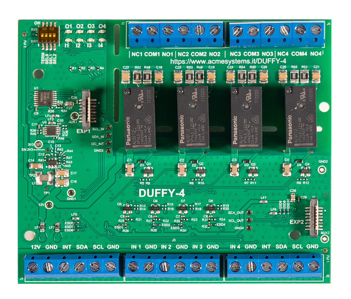 ## Features
* 4 relay output
* Normaly open and normaly closed screw terminals
* Panason ALQ112
* 10A 250VAC
* Surge 8,000 V, High breakdown voltage 4,000 V (Between contact and coil)
* RC snubber circuitry on NO and NC contacts to suppress voltage transients
* 4 clean contact input
* Electrostatic transient protections on each input
* I2C buffer
* Bus speed up to 400-kHz
* Input and output screw separate screw terminal
* On-board repeater buffer between input and output terminals
* Pitch 5mm screw terminals for all signals
* Double Acme FPC six connector for WiFi controller and Acme Sensors boards
* Power in 12VDC
* DIN rail case (6 module)
## I2C Addressing
Daffy-4 can use up to 8 different I2C addres setting the SW1 dip switch. The factory default
address is 0x38 (all SELx switches in OFF position)
| SEL2 (A2) | SEL1 (A1) | SEL0 (A0) | Hex Address | Dec Address |
|------------|-----------|-----------|-------------|-------------|
| ON (0) | ON (0) | ON (0) | 0x38 | 56 |
| ON (0) | ON (0) | OFF (1) | 0x39 | 57 |
| ON (0) | OFF (1) | ON (0) | 0x3A | 58 |
| ON (0) | OFF (1) | OFF (1) | 0x3B | 59 |
| OFF (1) | ON (0) | ON (0) | 0x3C | 60 |
| OFF (1) | ON (0) | OFF (1) | 0x3D | 61 |
| OFF (1) | OFF (1) | ON (0) | 0x3E | 62 |
| OFF (1) | OFF (1) | OFF (1) | 0x3F | 63 |
Each board has a I2C bi-directional buffer that regenerates the bus voltage levels provided to the next board
### Wire and search the DAFFY-4 board on Acme-Sensor 2 port
Set the Daffy-4 dip switches in this way:
| SEL 0 | SEL 1 | SEL 2 | Addess Hex | Address Dec |
|-------|-------|-------|------------|-------------|
| ON | ON | ON | 0x38 | 56 |
Wire the Daffy-4 board to the Acme sensor port 2
Scan the I2C bus to check the board presence:
sudo i2cdetect -y 1
0 1 2 3 4 5 6 7 8 9 a b c d e f
00: -- -- -- -- -- -- -- --
10: -- -- -- -- -- -- -- -- -- -- -- -- -- -- -- --
20: -- -- -- -- -- -- -- -- -- -- -- -- -- -- -- --
30: -- -- -- -- -- -- -- -- 38 -- -- -- -- -- -- --
40: -- -- -- -- -- -- -- -- -- -- -- -- -- -- -- --
50: -- -- -- -- -- -- -- -- -- -- -- -- -- -- -- --
60: -- -- -- -- -- -- -- -- -- -- -- -- -- -- -- --
70: -- -- -- -- -- -- -- --
### Python examples
Install python3-smbus package by typing:
sudo apt update
sudo apt install python3-smbus
Save this Python3 code inside a file called daffy.py:
import smbus
import time
DEVICE_BUS = 1 # /dev/i2c-1
# Board list
BOARD_ADDR=[56];
# Output value to send on each board
RELAY_OUT=[0x10,0x20,0x40,0x80,0x00];
Reg_InputPort = 0x00 # default 0x00
Reg_OutputPort = 0x01 # default 0xFF
Reg_PolarityInversion = 0x02 # default 0x00; polarity invert
Reg_Configuration = 0x03 # default 0xFF, 1 = input; 0 = output;
bus = smbus.SMBus(DEVICE_BUS)
for addr in BOARD_ADDR:
print("Send configuration to board: " + "0x{:02x}".format(addr))
bus.write_byte_data(addr, Reg_Configuration,0x0F)
while True:
for addr in BOARD_ADDR:
for relay_bitmap in RELAY_OUT:
print("Send " + "0x{:02x}".format(relay_bitmap) + " to board " + hex(addr))
bus.write_byte_data(addr, Reg_OutputPort,relay_bitmap)
time.sleep(0.2);
Turn on teh Acme sensor port 2
* Power line ON (PIOBU5)
## Features
* 4 relay output
* Normaly open and normaly closed screw terminals
* Panason ALQ112
* 10A 250VAC
* Surge 8,000 V, High breakdown voltage 4,000 V (Between contact and coil)
* RC snubber circuitry on NO and NC contacts to suppress voltage transients
* 4 clean contact input
* Electrostatic transient protections on each input
* I2C buffer
* Bus speed up to 400-kHz
* Input and output screw separate screw terminal
* On-board repeater buffer between input and output terminals
* Pitch 5mm screw terminals for all signals
* Double Acme FPC six connector for WiFi controller and Acme Sensors boards
* Power in 12VDC
* DIN rail case (6 module)
## I2C Addressing
Daffy-4 can use up to 8 different I2C addres setting the SW1 dip switch. The factory default
address is 0x38 (all SELx switches in OFF position)
| SEL2 (A2) | SEL1 (A1) | SEL0 (A0) | Hex Address | Dec Address |
|------------|-----------|-----------|-------------|-------------|
| ON (0) | ON (0) | ON (0) | 0x38 | 56 |
| ON (0) | ON (0) | OFF (1) | 0x39 | 57 |
| ON (0) | OFF (1) | ON (0) | 0x3A | 58 |
| ON (0) | OFF (1) | OFF (1) | 0x3B | 59 |
| OFF (1) | ON (0) | ON (0) | 0x3C | 60 |
| OFF (1) | ON (0) | OFF (1) | 0x3D | 61 |
| OFF (1) | OFF (1) | ON (0) | 0x3E | 62 |
| OFF (1) | OFF (1) | OFF (1) | 0x3F | 63 |
Each board has a I2C bi-directional buffer that regenerates the bus voltage levels provided to the next board
### Wire and search the DAFFY-4 board on Acme-Sensor 2 port
Set the Daffy-4 dip switches in this way:
| SEL 0 | SEL 1 | SEL 2 | Addess Hex | Address Dec |
|-------|-------|-------|------------|-------------|
| ON | ON | ON | 0x38 | 56 |
Wire the Daffy-4 board to the Acme sensor port 2
Scan the I2C bus to check the board presence:
sudo i2cdetect -y 1
0 1 2 3 4 5 6 7 8 9 a b c d e f
00: -- -- -- -- -- -- -- --
10: -- -- -- -- -- -- -- -- -- -- -- -- -- -- -- --
20: -- -- -- -- -- -- -- -- -- -- -- -- -- -- -- --
30: -- -- -- -- -- -- -- -- 38 -- -- -- -- -- -- --
40: -- -- -- -- -- -- -- -- -- -- -- -- -- -- -- --
50: -- -- -- -- -- -- -- -- -- -- -- -- -- -- -- --
60: -- -- -- -- -- -- -- -- -- -- -- -- -- -- -- --
70: -- -- -- -- -- -- -- --
### Python examples
Install python3-smbus package by typing:
sudo apt update
sudo apt install python3-smbus
Save this Python3 code inside a file called daffy.py:
import smbus
import time
DEVICE_BUS = 1 # /dev/i2c-1
# Board list
BOARD_ADDR=[56];
# Output value to send on each board
RELAY_OUT=[0x10,0x20,0x40,0x80,0x00];
Reg_InputPort = 0x00 # default 0x00
Reg_OutputPort = 0x01 # default 0xFF
Reg_PolarityInversion = 0x02 # default 0x00; polarity invert
Reg_Configuration = 0x03 # default 0xFF, 1 = input; 0 = output;
bus = smbus.SMBus(DEVICE_BUS)
for addr in BOARD_ADDR:
print("Send configuration to board: " + "0x{:02x}".format(addr))
bus.write_byte_data(addr, Reg_Configuration,0x0F)
while True:
for addr in BOARD_ADDR:
for relay_bitmap in RELAY_OUT:
print("Send " + "0x{:02x}".format(relay_bitmap) + " to board " + hex(addr))
bus.write_byte_data(addr, Reg_OutputPort,relay_bitmap)
time.sleep(0.2);
Turn on teh Acme sensor port 2
* Power line ON (PIOBU5) sudo gpioset gpiochip1 5=1
* Power line OFF (PIOBU5) sudo gpioset gpiochip1 5=0
Then type:
sudo python3 daffy.py
If you have two or more boards add their address on this line:
BOARD_ADDR=[56,57,58];
and set the switch on each board:
| Board # | SEL 0 | SEL 1 | SEL 2 | Addess Hex | Address Dec |
|---------|-------|-------|-------|------------|-------------|
| 1 | ON | ON | ON | 0x38 | 56 |
| 2 | OFF | ON | ON | 0x39 | 57 |
| 3 | ON | OFF | ON | 0x3A | 58 |
| ... | ... | ... | ... | ... | ... |
## Manage the Daffy-4 board using an ESP8266-12F
#include
#include
#include
#include
#include
//----SERIAL CONFIG ----
#define SERIAL_SPEED 115200
//----WIFI CONFIG ----
#define WIFI_SSID "acmetest"
#define WIFI_PASSWD "acmetest"
#define MAX_WIFI_INIT_RETRY 10
#define WIFI_RETRY_DELAY 500
//----MQTT CONFIG ----
#define MQTT_SERVER "192.168.1.95"
#define MQTT_UNAME ""
#define MQTT_PASSW ""
#define MQTT_BROKER_PORT 1883
#define MQTT_CLIENT_ID "1234"
WiFiClient wifi_client;
PubSubClient mqtt_client(wifi_client, MQTT_SERVER, MQTT_BROKER_PORT);
//unsigned long delayTime;
//Wifi Initialization function
int WiFi_init()
{
const char* wifi_ssid = WIFI_SSID;
const char* wifi_passwd = WIFI_PASSWD;
int retries = 0;
Serial.println("Connecting to WiFi AP..........");
WiFi.mode(WIFI_STA); //set wifi station mode
WiFi.begin(wifi_ssid, wifi_passwd); //start connecting to WiFi AP
//check the status of WiFi connection to be WL_CONNECTED
while ((WiFi.status() != WL_CONNECTED) && (retries < MAX_WIFI_INIT_RETRY)) {
retries++;
delay(WIFI_RETRY_DELAY);
Serial.println("#");
}
Serial.println(String(WiFi.localIP()[0]) + "." + String(WiFi.localIP()[1]) + "." + String(WiFi.localIP()[2]) + "." + String(WiFi.localIP()[3]));
return WiFi.status(); //return the WiFi connection status
}
void mqtt_callback(const MQTT::Publish& pub)
{
Serial.println("MQTT receiving a message:");
Serial.println(pub.payload_string());
if (pub.payload_string()=="ON") {
Wire.beginTransmission(0x38);
Wire.write(0x03);
Wire.write(0x0F);
Wire.endTransmission(); // stop transmitting
Wire.beginTransmission(0x38);
Wire.write(0x01);
Wire.write(0xF0);
Wire.endTransmission(); // stop transmitting
} else {
Wire.beginTransmission(0x38);
Wire.write(0x03);
Wire.write(0x0F);
Wire.endTransmission(); // stop transmitting
Wire.beginTransmission(0x38);
Wire.write(0x01);
Wire.write(0x00);
Wire.endTransmission(); // stop transmitting
}
}
void setup() {
Serial.begin(SERIAL_SPEED);
Wire.begin();
delay(100);
Serial.println("Program Start");
Wire.begin();
Wire.write(0x03);
Wire.write(0x0F);
// WiFi
while(true) {
Serial.println("WiFi try");
if (WiFi_init()==WL_CONNECTED) {
Serial.println("WiFi success");
break;
}
Serial.println("WiFi failed");
delay(1000);
}
// MQTT
while(true) {
Serial.println("MQTT try");
if (mqtt_client.connect(MQTT::Connect(MQTT_CLIENT_ID).set_keepalive(90).set_auth(String(MQTT_UNAME), String(MQTT_PASSW)))) {
mqtt_client.set_callback(mqtt_callback); //set callback on received messages
mqtt_client.set_max_retries(255);
if (mqtt_client.subscribe("/daffy/relay")) {
Serial.println("Subscription success");
break;
} else {
Serial.println("Subscription failed");
mqtt_client.disconnect();
delay(1000);
continue;
}
} else {
delay(1000);
continue;
}
}
}
void loop() {
char payload[20];
//sprintf(payload,"Start");
//mqtt_client.publish("/daffy/input", payload);
if (mqtt_client.connected()) {
mqtt_client.loop();
}
}
## Schematic
* [Daffy-4 schematic in PDF format](./daffy-4-schematic.pdf)
## Datasheet
* [Relay Panasonic ALQ112](http://www.farnell.com/datasheets/2245159.pdf)
* [Texas Instruments TCA9534A Low Voltage 8-Bit I2C and SMBUS Low-Power I/O Expander With Interrupt](https://www.ti.com/lit/ds/symlink/tca9534a.pdf)
@include='adv_relay'