 ## Features
* Power is: 5 Volt DC
* Power outs:
* 3.3 Volt @ 500 mA
* 1.8 Volt
* 1.0 Volt
* [NetusPS1 schematic](http://terzo.acmesystems.it/download/schematics/schematic_netusps1.pdf)
* [LM26480 Datasheet](http://terzo.acmesystems.it/download/datasheets/lm26480.pdf)
Buy
##Pinout
| Pin | Line | in/out | Notes |
|-----|------|--------|-------|
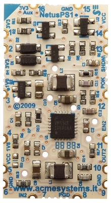
| 1-2 | 3V3 | powerout | Main 3V3 out for Netus G20 power and peripherals who need to be powered at the same time of the Netus G20. Max current available for peripherals: 500mA |
| 3 | 1V0 | powerOut | Main 1V0 out for Netus G20. Not for powering other peripherals |
| 4 | 1V8 | powerOut | Main 1V8 out for Netus G20. Not for powering other peripherals |
| 5 | 5V | powerIN | Main input voltage 5 Volts stabilized (connected also to pin 14) |
| 6 | GND | ground | Ground (connected also to pins 9 and 15) |
| 7 | IN2 | powerIN | Input for the spare Low DropOut regulator (normally connected to 5V) |
| 8 | PGD | signalOUT| Output showing the 5V input is now stable |
| 9 | GND | ground | ground (connected also to pins 6 and 15) |
|10 | OUT2 | powerOUT | Output for the spare Low DropOut regulator (factory trimmed to 3.25V). Max power deliverable 250mA |
|11 | EN2 | signalIN | Enable input active High (+5V) for the spare Low DropOut regulator |
|12 | POK | signalOUT| Output signaling that the NetusPS1 outputs 3V3, 1V8 and 1V0 are now permitted to start (see figure 3) |
|13 | SHDN\ | signalIN | Shutdown input (active Low) When lowered to ground NetusPS1 outputs 3V3, 1V8 and 1V0 are switched off. Releasing this pin will restart the correct power up sequence for those three power outputs |
|14 | VCC | powerIN | Main input voltage 5Volts stabilized (connected also to pin 5) |
|15 | GND | ground | Ground (connected also to pins 6 and 9) |
|16 | 3V3Aux | powerOUT | Auxiliary 3V3 power output always present even when SHDN\ is lowered to ground |
#Power sequences
Each power-out line have to follows a timing sequence, any deviation from these sequences may lead excessive current consumption during power-up or freeze the device while booting:
* [Read Atmel specification for more info](http://terzo.acmesystems.it/download/datasheet/MigrationTo9G20doc6415.pdf)
## Features
* Power is: 5 Volt DC
* Power outs:
* 3.3 Volt @ 500 mA
* 1.8 Volt
* 1.0 Volt
* [NetusPS1 schematic](http://terzo.acmesystems.it/download/schematics/schematic_netusps1.pdf)
* [LM26480 Datasheet](http://terzo.acmesystems.it/download/datasheets/lm26480.pdf)
Buy
##Pinout
| Pin | Line | in/out | Notes |
|-----|------|--------|-------|
| 1-2 | 3V3 | powerout | Main 3V3 out for Netus G20 power and peripherals who need to be powered at the same time of the Netus G20. Max current available for peripherals: 500mA |
| 3 | 1V0 | powerOut | Main 1V0 out for Netus G20. Not for powering other peripherals |
| 4 | 1V8 | powerOut | Main 1V8 out for Netus G20. Not for powering other peripherals |
| 5 | 5V | powerIN | Main input voltage 5 Volts stabilized (connected also to pin 14) |
| 6 | GND | ground | Ground (connected also to pins 9 and 15) |
| 7 | IN2 | powerIN | Input for the spare Low DropOut regulator (normally connected to 5V) |
| 8 | PGD | signalOUT| Output showing the 5V input is now stable |
| 9 | GND | ground | ground (connected also to pins 6 and 15) |
|10 | OUT2 | powerOUT | Output for the spare Low DropOut regulator (factory trimmed to 3.25V). Max power deliverable 250mA |
|11 | EN2 | signalIN | Enable input active High (+5V) for the spare Low DropOut regulator |
|12 | POK | signalOUT| Output signaling that the NetusPS1 outputs 3V3, 1V8 and 1V0 are now permitted to start (see figure 3) |
|13 | SHDN\ | signalIN | Shutdown input (active Low) When lowered to ground NetusPS1 outputs 3V3, 1V8 and 1V0 are switched off. Releasing this pin will restart the correct power up sequence for those three power outputs |
|14 | VCC | powerIN | Main input voltage 5Volts stabilized (connected also to pin 5) |
|15 | GND | ground | Ground (connected also to pins 6 and 9) |
|16 | 3V3Aux | powerOUT | Auxiliary 3V3 power output always present even when SHDN\ is lowered to ground |
#Power sequences
Each power-out line have to follows a timing sequence, any deviation from these sequences may lead excessive current consumption during power-up or freeze the device while booting:
* [Read Atmel specification for more info](http://terzo.acmesystems.it/download/datasheet/MigrationTo9G20doc6415.pdf)
| ##Power-up sequence | ##Power-down sequence |
|---|---|
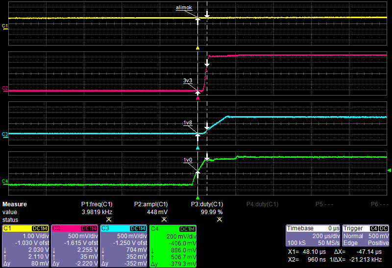
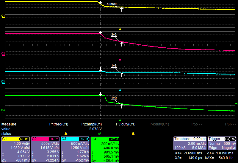
| 1V0 power out is the first to start, when it reaches 0.5 Volts, the other two power out line 1V8 and 3V3 go on. These two power lines reach 0,7 Volts within 50 us and become steady up well within 300 us. The **POK** signal is generated by an on-board power supervisor chip (CAT811TTBI) when the VCC input (5 Volt DC) is stable. | The 3V3 and 1V8 power out line switchs off at the same time of 1V0 voltage. |
|
|
|