Please note !
Starting from July 2018 we make by default just color green Ariettas G25. The only difference between
the legacy black version (ARIETTA-G25) and the new green version (ARIETTA-G25-V) is the solder mask color.
To order the legacy black version a Minimal Quantity Order of 100 pcs is requested.
##Main features
* [Long term availability](/declarations/ProductsAvailability.pdf)
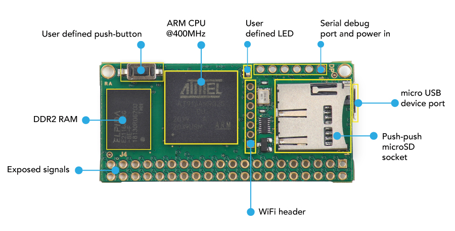
* [Microchip AT91SAM9G25 MPU](http://www.microchip.com/wwwproducts/en/AT91SAM9G25) (ARM9@400Mhz)
* DDR2 RAM 128/256 MB @ 16 bit
* MicroSD holder push-pull type
* MicroUSB device port for power-in and gadget device
* User configurable led
* User configurable push-button
* Power supply: 5VDC via microUSB or 3.3VDC using the [PCB pads](/pinout_arietta)
* Line levels: TTL 3.3V (NOT 5V tolerant)
* Operative temperature range:
* ARIETTA-G25 (128MByte RAM): -20 +70 °C
* ARIETTA-G25-256 (256MByte RAM): -0 +70 °C
* Size: 53x25mm
* PCB layers: 8
* RoHS and REACH compliant. Low EMI
* Designed and Made in Italy
* [Declarations of conformity](/declarations)
##Exposed signals
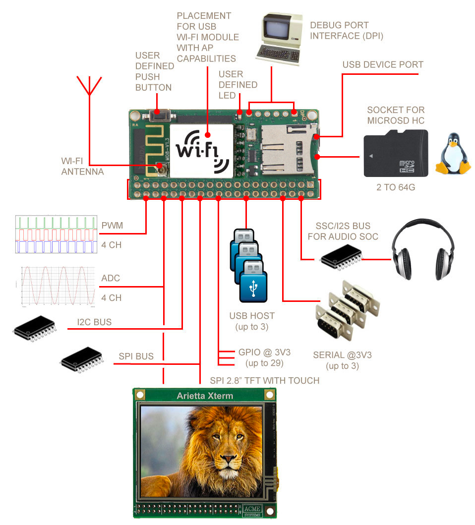
* __J4__ Placement for a 20x2 pins connector pitch 2.54mm (100 mils) ([pinout](/pinout_arietta)):
* 1 full-speed usb host
* 1 hi-speed host/device (same port lines used for the microUSB port)
* 1 hi-speed host (same lines used for the WiFi adapter)
* UART lines: 3 ports
* I2C bus lines: 2 bus
* SPI bus lines: 1 bus with up to 3 chip select (5 to 50 MHz)
* PWM lines: 4 lines
* A/D converters lines: 4 channels@10 bit
* SSC/I2S interface for audio soc
* No video or TFT output but the SPI bus can be used for small TFT display and I2C bus for small alphanumeric LCD
* No direct LAN interface but the USB ports can be used with USB to LAN adapter
* __DP__ placements for a 6 pin male strip pitch 2.54 (100 mils) with the [Debug Port Interface](/DPI) lines
* Placement for [IEE802.11 b/g/n Wi-Fi module](/arietta_wifi) WiFi USB adapter
 Please note that not all the signales are available at the same time. Some line are muxed together.
##Pin muxing
Most of the Arietta lines on J3 can be configured for additional functions
using the muxing cabability of the Atmel MPU. The default configuration
depends from the __at91-arietta.dtb__ file stored on the first micro SD
partition and used at startup by the Linux Kernel.
The [Arietta dynamic pinout page](/pinout_arietta) may helps you to
understand what are the available peripherals and how to generate this
file.
@include='software_features'
Please note that not all the signales are available at the same time. Some line are muxed together.
##Pin muxing
Most of the Arietta lines on J3 can be configured for additional functions
using the muxing cabability of the Atmel MPU. The default configuration
depends from the __at91-arietta.dtb__ file stored on the first micro SD
partition and used at startup by the Linux Kernel.
The [Arietta dynamic pinout page](/pinout_arietta) may helps you to
understand what are the available peripherals and how to generate this
file.
@include='software_features'