Arduino > Preferences... > Additional Board Manager URLs: and
add the following URL for the ATtiny core by Spence Konde (DrAzzy):
http://drazzy.com/package_drazzy.com_index.json
Click "OK" to close the Preferences window.
Open the Board Manager by navigating to Tools > Board > Boards Manager....
In the Boards Manager window search for ATtiny and select ATTinyCode by Spence Konde then press then
.
Now navigate to Tools > Boards > ATTinyCore > ATtiny48/88 (Optiboot)
Configure the processor settings
* Tools > Chip > ATTiny88
* Tools > Clock Source > 4MHz (Internal)
Copy inside the editor this sketch:
* [pwr.ino](./pwr.ino)
then select the menu Sketch > Verify/Compile
Sketch uses 4342 bytes (53%) of program storage space. Maximum is 8192 bytes.
Global variables use 292 bytes (57%) of dynamic memory, leaving 220 bytes for local variables. Maximum is 512 bytes.
then Sketch > Export compiled Binary.
then Sketch > Show sketch folder and check that the file pwr.ino.hex exist.
If you have a Tiny USB programmer you code inject the code directly by hardware to the co-processor using the J4 Prog port on CM-Panel POE.
If not transfer the file pwr.ino.hex to the CM-Panel POE microSH using SSH and program the co-processor using avrdude.
## How to inject the code inside the ATTiny88 co-processor
There are some ways to transfer the binary code inside the ATTiny flash memory:
1. Using the Tiny USB cheap ISP programmer and Arduino IDE
1. Using the Tiny USB cheap ISP programmer and the CM-Panel itself
1. Using an USB to serial converter and the Arduino IDE
1. Using an USB to serial converter and the CM-Panel itself
Methods 3 and 4 are possible because the ATTiny become already programmed with the ATTiny firmware + Optiboot loader
Methods 1 and 2 works also with a fully blank ATTiny
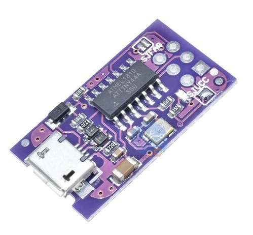 In case of ISP using the CM-Panel itself install
 avrdude by typing:
$ sudo apt update
$ sudo apt install avrdude
Download the avrdude configuration file from our site by typing:
$ wget https://www.acmesystems.it/www/cmpanel-poe_attiny/avrdude.conf
Download the ATTiny firmware from our site by typing:
$ wget https://www.acmesystems.it/www/cmpanel-poe_attiny/pwr.ino.hex
Insert the Tiny USB programmer between one of the USB port of CM-Panel and the J4 PROG port
and type:
$ sudo avrdude -Cavrdude.conf -v -pattiny88 -cusbtiny -e -Uefuse:w:0xfe:m -Uhfuse:w:0b11010111:m -Ulfuse:w:0xE2:m -Uflash:w:pwr.ino.hex:i
or insert an USB to serial adapted between an USB port on CM-Panel POE and the ATTiny debug port available on EXP2
header, open the PROG BYPASS jumper, then type:
$ sudo avrdude -Cavrdude.conf -v -pattiny88 -carduino -P/dev/ttyUSB0 -b19200 -D -Uflash:w:pwr.ino.hex:i
and reset the ATTiny by pressing the reset button near the supercap (@article='cmpanel-poe_jumpers_headers_pushbuttons').
## ATTiny debug port
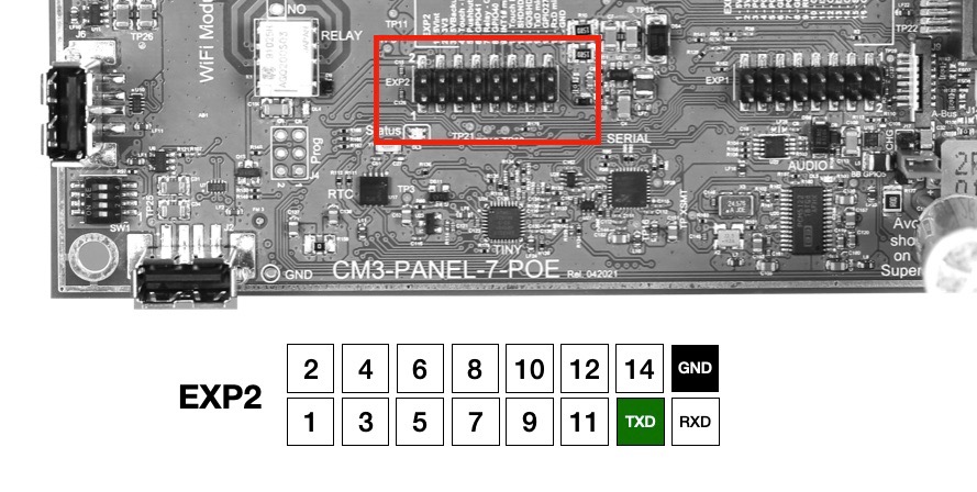
The coprocessor has a debug serial port whose signals are exposed on the EXP2 connector as shown in the figure.
These signals are at 3.3 volts with the following serial parameters:
19200 baud,N,8,1 no flow control.
 ## Notes
Get the stand alone optiboot binary file:
$ wget https://www.acmesystems.it/www/cmpanel-poe_attiny/optiboot_attiny88_8000000L.hex
Programming just the Optiboot bootloader width Atmel ICE
$ sudo avrdude -Cavrdude.conf -v -pattiny88 -catmelice_isp -Pusb -e -Uefuse:w:0xfe:m -Uhfuse:w:0b11010111:m -Ulfuse:w:0xE2:m -Uflash:w:optiboot_attiny88_8000000L.hex:i
Programming just the bootloader with USBTiny
$ sudo avrdude -Cavrdude.conf -v -pattiny88 -cusbtiny -e -Uefuse:w:0xfe:m -Uhfuse:w:0b11010111:m -Ulfuse:w:0xE2:m -Uflash:w:optiboot_attiny88_8000000L.hex:i
## Downloads
* ATTiny co-processor firmware: [pwr.ino](./pwr.ino)
* ATTiny co-processor binary code (includes optiboot): [pwr.ino.hex](./pwr.ino.hex)
* Stand alone optiboot binary code: [optiboot_attiny88_8000000L.hex](./optiboot_attiny88_8000000L.hex)
* Avrdude configuration file: [avrdude.conf](./avrdude.conf)
## Links
* Optiboot
## Notes
Get the stand alone optiboot binary file:
$ wget https://www.acmesystems.it/www/cmpanel-poe_attiny/optiboot_attiny88_8000000L.hex
Programming just the Optiboot bootloader width Atmel ICE
$ sudo avrdude -Cavrdude.conf -v -pattiny88 -catmelice_isp -Pusb -e -Uefuse:w:0xfe:m -Uhfuse:w:0b11010111:m -Ulfuse:w:0xE2:m -Uflash:w:optiboot_attiny88_8000000L.hex:i
Programming just the bootloader with USBTiny
$ sudo avrdude -Cavrdude.conf -v -pattiny88 -cusbtiny -e -Uefuse:w:0xfe:m -Uhfuse:w:0b11010111:m -Ulfuse:w:0xE2:m -Uflash:w:optiboot_attiny88_8000000L.hex:i
## Downloads
* ATTiny co-processor firmware: [pwr.ino](./pwr.ino)
* ATTiny co-processor binary code (includes optiboot): [pwr.ino.hex](./pwr.ino.hex)
* Stand alone optiboot binary code: [optiboot_attiny88_8000000L.hex](./optiboot_attiny88_8000000L.hex)
* Avrdude configuration file: [avrdude.conf](./avrdude.conf)
## Links
* Optiboot @include='adv_cmpanel'