# Raspberry Pi OS for CM-Panel POE
This article explains how to create a microSD with Raspberry PI OS for the CM-Panel POE starting from an official image for Raspberry Pi.
Download and install on your PC the Raspberry Pi Imager from this url:
*
then launch it.
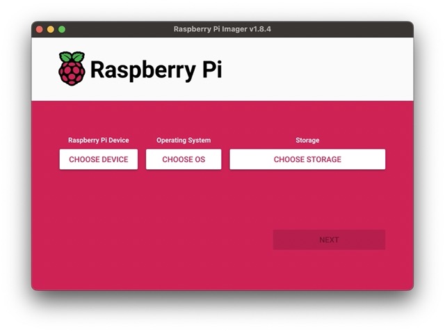 If on your CM-Panel is mounted a Raspberry CM4S module press the
 CHOOSE DEVICE button and select Raspberry Pi 4
Press the CHOOSE OS button and select the Raspberry Pi OS you like. In this
example we will use Raspberry Pi OS (other) -> Raspberry Pi OS Lite (64-bit)
Insert in your PC the blank microSD and press the CHOOSE STORAGE button and select
the microSD storage.
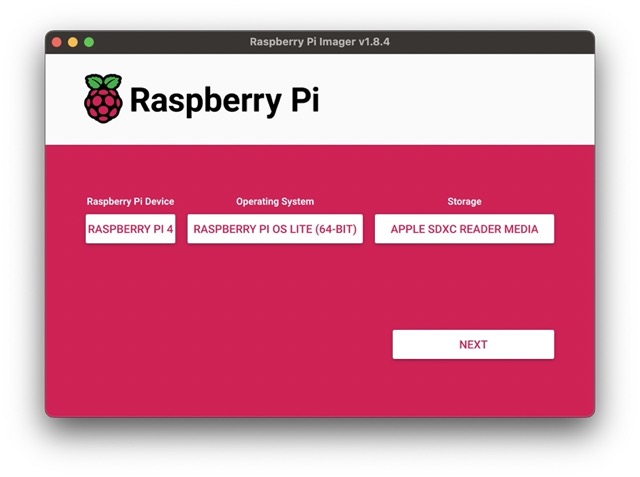 Press the
 NEXT button.
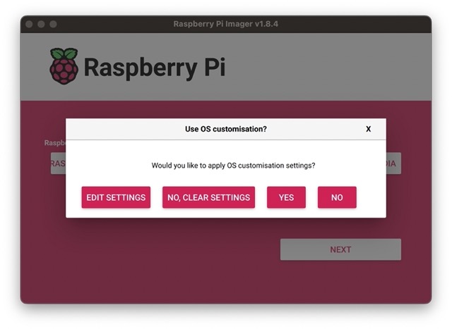 Press the
 EDIT SETTINGS button.
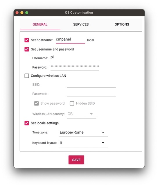 In this form set the hostname of your CM Panel, the user and password.
If a WiFi module is mounted on CM Panel POE insert the name of your WiFi (SSID) and the password to get the access.
Switch to the tab SETTINGS and enable the SSH access.
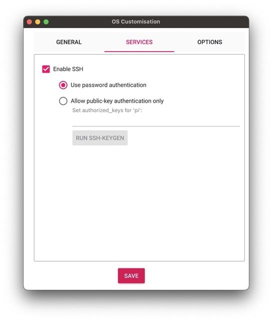 Press the
 SAVE button the the YES button.
The YES again.
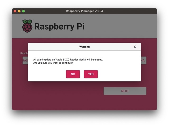 After the writing and verifying operation, remove the microSD card and insert it again to see the content of the first microSD partition
called
After the writing and verifying operation, remove the microSD card and insert it again to see the content of the first microSD partition
called bootfs the make these changes on the stardard files present on this partition.
### Changes on config.txt file
Open the file config.txt with a text editor and change its content with this:
# For more options and information see
# http://rptl.io/configtxt
# Some settings may impact device functionality. See link above for details
dtoverlay=gpio-shutdown,gpio_pin=25,active_low=1,gpio_pull=up
#dtoverlay=gpio-poweroff,gpio_pin=26,active_low=1
# Uncomment some or all of these to enable the optional hardware interfaces
dtparam=i2c_arm=on
#dtparam=i2s=on
#dtparam=spi=on
# Disable the default audio driver (snd_bcm2835)
dtparam=audio=off
# Enable the audio codec
dtoverlay=i2s-gpio28-31
dtoverlay=hifiberry-dacplus
# RS232/RS485/RS422 port on /dev/ttyAMA0
force_turbo=1
dtoverlay=uart0,txd0_pin=36,rxd0_pin=37,pin_func=6
# Automatically load overlays for detected cameras
camera_auto_detect=1
dtoverlay=ov5647
# Automatically load initramfs files, if found
auto_initramfs=1
# Enable DRM VC4 V3D driver
dtoverlay=vc4-kms-v3d
dtoverlay=vc4-kms-dpi-generic
max_framebuffers=2
#display_lcd_rotate=2
# Run in 64-bit mode
arm_64bit=1
# Disable compensation for displays with overscan
disable_overscan=1
# Run as fast as firmware / board allows
arm_boost=1
[cm4]
# Enable host mode on the 2711 built-in XHCI USB controller.
# This line should be removed if the legacy DWC2 controller is required
# (e.g. for USB device mode) or if USB support is not required.
otg_mode=1
[all]
#Ignore the HDMI cable hotplug (to avoid the delay at startup)
hdmi_ignore_hotplug=1
# Set the debug port on GPIO32, GPIO33 pins
force_turbo=1
dtoverlay=uart1,txd1_pin=32,rxd1_pin=33
# Activates the I2C 1 port on GPIO44 and 45 to talk with the
# touch screen controller end camera crypto-chip
dtoverlay=i2c1,pins_44_45
dtoverlay=goodix-7-acme
## Enable the DPI port to talk with the TFT display
dtoverlay=dpi18
overscan_left=0
overscan_right=0
overscan_top=0
overscan_bottom=0
framebuffer_width=800
framebuffer_height=480
enable_dpi_lcd=1
display_default_lcd=1
dpi_group=2
dpi_mode=87
dpi_output_format=0x6f005
hdmi_timings=800 0 40 48 88 480 0 13 3 32 0 0 0 60 0 32000000 6
### Changes on cmdline.txt file
Open cmdline.txt and change this line:
console=serial0,115200
in:
console=serial1,115200
In this way the serial console messages will be transmitted on the DEBUG_TX and DEBUG_RX lines available
on the EXP2 connector.
### Add goodix-7-acme.dtbo overlay blog file
Goodix is the brand of I2C chip mounted to the touchscreen. The file
goodix-7-acme.dtbo is used to enable the Goodix I2C Linux driver and use the rigth
lines and I2C address.
Download and save goodix-7-acme.dtbo in the overlays directory:
* [overlays/goodix-7-acme.dtbo](./goodix-7-acme.dtbo)
If your like to check the device tree source used to generate this file click on this link:
* [overlays/goodix-7-acme.dts](./goodix-7-acme.dts)
To generate the .dtbo file from thr .dts source use this command:
sudo dtc -@ -I dts -O dtb -o /boot/overlays/goodix-7-acme.dtbo /boot/overlays/goodix-7-acme.dts
### Add the dt-blob.bin blog file
The file dt-blob.bin defines the lines used by the Raspberry camera for the I2C bus on the CM-Panel.
Download and save it in the boot directory:
* [dt-blob.bin](./dt-blob.bin)
of your prefere you can compile it from this source:
* [dt-blob.dts](./dt-blob.dts)
To compile it you need a Linux PC or a Raspberry Pi and a Device Tree Compiler:
sudo dtc -I dts -O dtb -o /boot/dt-blob.bin /boot/dt-blob.dts
### Enable the safe shutdown
To enable the safe shutdown features read this article:
* @article='cmpanel-poe_safe_shutdown'
### Bootstrap
Umount the microSD from your PC and boot it on your CM-Panel
@include='adv_cmpanel'