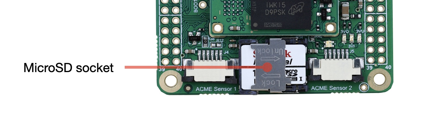
 Check the messages generated during the boot using the serial console port.
Any commercial USB/serial adapter at 3.3 volt can be used. On this site is available
this product: @article='USB-3V-SER'.
Configure your terminal emulator at
Check the messages generated during the boot using the serial console port.
Any commercial USB/serial adapter at 3.3 volt can be used. On this site is available
this product: @article='USB-3V-SER'.
Configure your terminal emulator at 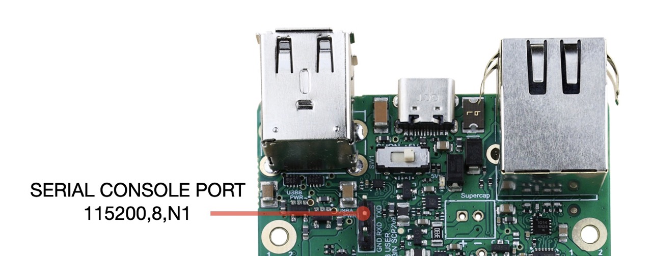
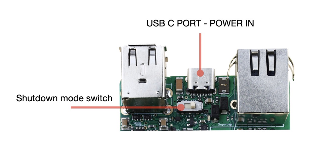
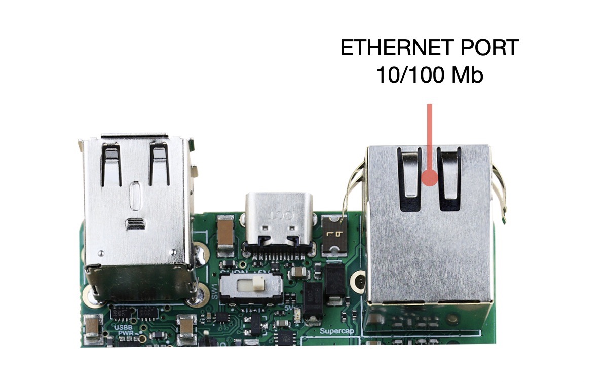 Provide the power to the board using an USB-C power supply. Check that the SHUTDOWN switch is turned on
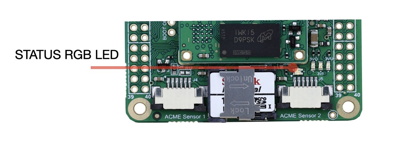
  During the bootstrap a small RGB led will blink in this way:
* Red blinks indicates activities on microSD
* Green blinks indicates the CPU load
During the bootstrap a small RGB led will blink in this way:
* Red blinks indicates activities on microSD
* Green blinks indicates the CPU load
 ## Get the access from the console port:
During the boot a lot of messages are sent over the serial port by the Linux Kernel. After a while
a login message will appear:
foxd27 login: acme
Password: acmesystems
The command line prompt will appear waiting for your linux commands:
acme@foxd27:
Check for example your ip address by typing:
acme@foxd27: sudo ifconfig
eth0: flags=4163
## Get the access from the console port:
During the boot a lot of messages are sent over the serial port by the Linux Kernel. After a while
a login message will appear:
foxd27 login: acme
Password: acmesystems
The command line prompt will appear waiting for your linux commands:
acme@foxd27:
Check for example your ip address by typing:
acme@foxd27: sudo ifconfig
eth0: flags=4163192.168.10.83 and the MAC address is fc:c2:3d:54:3f:64.
This MAC address is world-wide unique for this board thanks to the [Microchip AT24MAC402](http://www.atmel.com/Images/Atmel-8807-SEEPROM-AT24MAC402-602-Datasheet.pdf)
mounted on the FOX D27. This chip contains also a unique 128-bit Serial Number and 2-kilobit of
serial EEPROM avalable for the user.
It is possible to know the IP address also using this command ip addr.
## Using the USB port
Fox Board D27 has two USB 2.0 host ports. They are called USB-A and USB-B and are located as shown below:
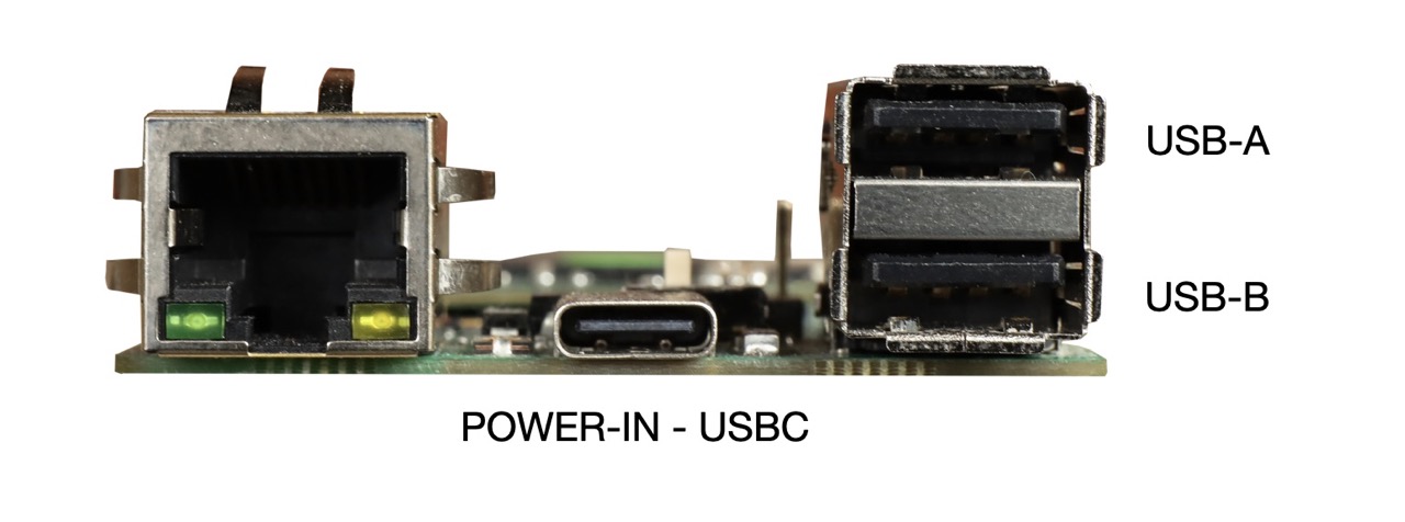 Each port can be turned-off by changing the logical state of some GPIO lines. By default both ports are on.
USB-A power line control (line PB25)
* ON
Each port can be turned-off by changing the logical state of some GPIO lines. By default both ports are on.
USB-A power line control (line PB25)
* ON sudo gpioset gpiochip0 57=1
* OFF sudo gpioset gpiochip0 57=0
USB-B power line control (line PB24)
* ON sudo gpioset gpiochip0 56=1
* OFF sudo gpioset gpiochip0 56=0
The port USB-A can work as host port ot client port. In this case the connector used is the USB-C power in connector.
Switch the USB-A line from the host connector to the device USBC connector (line PIOBU6)
* USB-A on host port sudo gpioset gpiochip1 6=0
* USB-A on device port sudo gpioset gpiochip1 6=1
To configure Linux to use the USB-A line as an USB client it is requested to change the Device Tree.
### Manage the 3V3_USER power line
On J1 and J2 GPIO connectors there are two pins where is available a 3.3 volt power line interruptible by software
usign the GPIO line PIOBU3. This line manages directly the ENABLE pin of PMIC that will provide the 3V3_USER powersupply.
* 3V3_USER ON sudo gpioset gpiochip1 3=1
* 3V3_USER OFF sudo gpioset gpiochip1 3=0
It is possible to check the state of this power out line by the green led 3VU
## Manage the green leds used to display the power line states
Three green leds are used to display the state of some power lines inside the FOX Board D27
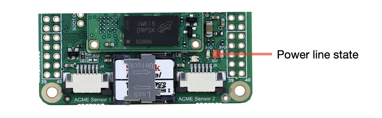 * 3VO - State of the 3.3 volt out from the [Roadrunner SOM](/roadrunner)
* 3VI - State of the 3.3 volt input line to the [Roadrunner SOM](/roadrunner)
* 3VU - State of the J1.1 and J2.1 3.3 volt user power out line
to limit the current absorption is it possible to turn-off this leds using this command (line PA26):
* ALL LEDS ON
* 3VO - State of the 3.3 volt out from the [Roadrunner SOM](/roadrunner)
* 3VI - State of the 3.3 volt input line to the [Roadrunner SOM](/roadrunner)
* 3VU - State of the J1.1 and J2.1 3.3 volt user power out line
to limit the current absorption is it possible to turn-off this leds using this command (line PA26):
* ALL LEDS ON sudo gpioset gpiochip0 26=1
* ALL LEDS OFF sudo gpioset gpiochip0 26=0
## Manage the RGB status led
The RGB status led uses three GPIO lines:
* PC9 red led
* PA25 green led
* PB13 blue led
by default this three lines is managed by the GPIO LED drived provided by Linux and activated inside the device tree
by these lines:
leds {
compatible = "gpio-leds";
pinctrl-names = "default";
pinctrl-0 = <&pinctrl_led_gpio_default>;
status = "okay";
red {
label = "red";
gpios = <&pioA PIN_PC9 GPIO_ACTIVE_LOW>;
linux,default-trigger = "mmc0";
};
green {
label = "green";
gpios = <&pioA PIN_PA25 GPIO_ACTIVE_LOW>;
linux,default-trigger = "heartbeat";
};
blue {
label = "blue";
gpios = <&pioA PIN_PB13 GPIO_ACTIVE_LOW>;
linux,default-trigger = "none";
};
};
It is possible to change the default trigger (in other words the way to use these leds) changing the device three or using the filesystem three available on /sys/class/leds.
ls /sys/class/leds
blue green mmc0:: red
### Examples:
Turn on the blue led:
sudo sh -c "echo '1' >> /sys/class/leds/blue/brightness"
Turn off the blue led:
sudo sh -c "echo '0' >> /sys/class/leds/blue/brightness"
Disable the trigger for the red amd green led:
sudo sh -c "echo 'none' >> /sys/class/leds/red/trigger"
sudo sh -c "echo 'none' >> /sys/class/leds/green/trigger"
Turn off the green and red leds:
sudo sh -c "echo '0' >> /sys/class/leds/green/brightness"
sudo sh -c "echo '0' >> /sys/class/leds/red/brightness"
Read the trigger enable for the red led
cat /sys/class/leds/red/trigger
[none] rfkill-any rfkill-none kbd-scrolllock kbd-numlock kbd-capslock kbd-kanalock kbd-shiftlock kbd-altgrlock kbd-ctrllock kbd-altlock kbd-shiftllock kbd-shiftrlock kbd-ctrlllock kbd-ctrlrlock timer heartbeat gpio cpu cpu0 mmc0
Removing the device tree association with the gpio-leds Linux driver inside the device tree might be possible to control the status led using directly these commands:
* RED ON (PC9) sudo gpioset gpiochip0 73=0
* RED OFF (PC9) sudo gpioset gpiochip0 73=1
* GREEN ON (PA25) sudo gpioset gpiochip0 25=0
* GREEN OFF (PA25) sudo gpioset gpiochip0 25=1
* BLUE ON (PB13) sudo gpioset gpiochip0 45=0
* BLUE OFF (PB13) sudo gpioset gpiochip0 45=1
Related products
@include='card_foxd27'
@include='card_roadrunner'
@include='card_bertad2'