#GPIO lines
This article explains how to manage the General Purpose Input/Output (GPIO) lines on the Acme boards
It contains just simple and quickly examples written in **Python** using the [ablib](https://github.com/tanzilli/ablib) module available on [github](/playground).
An in-deep explanation on how the GPIO lines work and how to manage them faster is available on:
* [Aria G25 GPIO notes by Dougg Gilbert](http://sg.danny.cz/foxg20/ag25g20_utils/ariag25_gpio.txt)
* [FOX Board G20 GPIO notes by Dougg Gilbert](http://sg.danny.cz/foxg20/foxg20_gpio.txt)
#Aria G25 examples
Using this basic example of wiring:
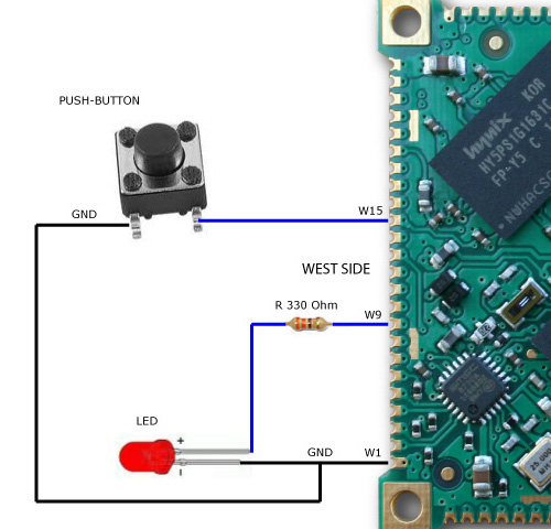 it is possible to define the **W9** line as an output and turn on/off the red led with the following code:
from ablib import Pin

led = Pin('W9','OUTPUT')
led.on()
led.off()
to read the button state it is possible to follow two methods:
* Polling mode
* Event mode
###Polling mode
This mode consists to check the actual state of the line calling the **get_value()** method.
from ablib import Pin

PB=Pin('W15','INPUT')

#Never ending loop
while True:
	if (PB.digitalRead()==0):
		print "Pressed"
		while digitalRead()==0:
			pass
###Event mode
This mode consists to register a callback function with the **set_edge()** method that will call when the GPIO lines changes its state.
from ablib import Pin
from time import sleep

def pressed():
	print "Pressed"

PB=Pin('W15','INPUT')
PB.set_edge("falling",pressed)

#Never ending loop
i=0
while True:
	print i
	i=i+1
	sleep(0.5)
One of three conditions can be checked:
* **falling**: the callback function is called when the signal goes from 1 to 0
* **rising**: the callback function is called when the signal goes from 0 to 1
* **both**: the callback function is called on any status change
#FOX Board G20 examples
Using this basic example of wiring:
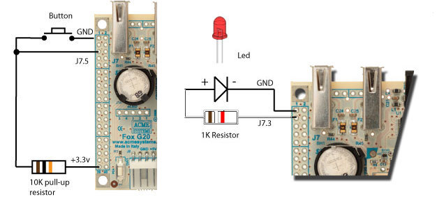 it is possible to refere to the pair connector/pin using this code to setup a GPIO as output
and drive a led:
it is possible to refere to the pair connector/pin using this code to setup a GPIO as output
and drive a led:
from ablib import Pin

led = Pin('J7.3','OUTPUT')
led.on()
led.off()
If you are using a [FOX Board G20](/FOXG20) with the [DAISY-1](/DAISY-1) adapter mounted on top the GPIO lines are available on the Daisy connectors ([pinout](/daisy1_pinout)).
In is possible to get a GPIO line using for example a [DAISY-12 protoboard](/DAISY-12) and set the GPIO line using the **on()** and **off()** methods of **Pin** class:
from ablib import Pin

led = Pin('D5.2','OUTPUT')
led.on()
led.off()
#TERRA Board
On the [TERRA Board](/terra) the GPIO lines are available on the Daisy connectors ([see the Terra pinout](/terra_pinout)).
It is possible to access directly the GPIO lines using for example the [DAISY-12 protoboard](/DAISY-12) and set the GPIO line using the **on()** and **off()** methods of **Pin** class:
from ablib import Pin

led = Pin('D11.2','OUTPUT')
led.on()
led.off()
to read the line state it is possible to follow two methods:
* Polling mode
* Event mode
##Polling mode
This mode consists to check the actual state of the line calling the get_value() method.
from ablib import Pin

PB=Pin('D11.3','INPUT')

#Never ending loop
while True:
    if (PB.digitalRead()==0):
        print "Pressed"
        while PB.digitalRead()==0:
            pass
##Event mode
This mode consists to register a callback function with the set_edge() method that will call when the GPIO lines changes its state.
from ablib import Pin
from time import sleep

def pressed():
    print "Pressed"

PB=Pin('D11.3','INPUT')
PB.set_edge("falling",pressed)

#Never ending loop
i=0
while True:
    print i
    i=i+1
    sleep(0.5)
If you are using a Daisy module with leds, relays or other output devices you can use directly the name of the devices written on the PCB silk screen.
Following is an example to turn on a led on the [DAISY-11 eight leds module](/DAISY-11):
from ablib import Daisy11

led = Daisy11('D11','L1')
led.on()
led.off()
This is an example with a [Daisy-8 relay board](/DAISY-8) plugged on D12 connector
from ablib import Daisy8

relay = Daisy8('D12','first','RL0')
relay.on()
relay.off()
The 'first' parms indicated that the Daisy8 used is plugged as first board on the flat cable. Up to board can be wired on the same daisy cable: 'first' and 'second'.
On FOX Board G20 only the **both** condition is available.
#How to configure the CPU pin at linux startup
The Atmel CPUs used on the Acme boards arranges the GPIO in ports of 32 lines each called Port A, Port B, Port C, etc.
Most of the CPU pins are muxed with other peripherals (UART, I2C, SPI, etc.) and can be configured as simple GPIO line
changing the Kernel configuration at boot time.
* On the FOX Board G20 with Linux Kernel 2.6.38 the pin config is defined on this file:
* [board-foxg20.c](https://github.com/tanzilli/foxg20-linux-2.6.38/blob/acme-2.6.38/arch/arm/mach-at91/board-foxg20.c)
* On the Aria G25 with Linux Kernel 2.6.39 the pin config is defined on this file:
* [at91sam9x5_devices.c](https://github.com/tanzilli/ariag25-linux-2.6.39/blob/ariag25/arch/arm/mach-at91/at91sam9x5_devices.c)
# Related links
* [GPIO Kernel doc](https://github.com/tanzilli/foxg20-linux-2.6.38/blob/acme-2.6.38/Documentation/gpio.txt#L546)
@include='tanzilli'