# How to design the microSD circuitry
In a Linux embedded systems based on [Roadrunner](https://www.acmesystems.it/roadrunner) SOM, or similar, very often the OS starts from an SD card. The speed class of the SD card can, of course, improve the responsiveness of a system that often makes access to such a memory support, but a bad design can lead to a worse performance of the whole system. Let's show some practical design principles for both schematics and PCB.
##Introduction
The SD card interface technology is rapidly expanding since its introduction in the beginning of this century. The standards defined time by time by [SD Association](https://www.sdcard.org/) are even more, rapidly increasing transfer speed and memory size. A quick tour of the current standards is available on [Wikipedia](https://en.wikipedia.org/wiki/Secure_Digital). Deeper descriptions can be found in the SD Association documents linked below.
The [**Roadrunner SOM**](https://www.acmesystems.it/roadrunner) uses a Microchip SAMA5D27 MCU. As described on [SAMA5D2 Series datasheet](http://ww1.microchip.com/downloads/en/DeviceDoc/60001476A.pdf) it has two **S**ecure **D**igital **M**ulti**M**edia **C**ard Controllers (SDMMC), with some little differences between them. Further SD cards can be used also with SPI connections.
The complete list of supported standards is available on chapter 51 of the datasheet. This list can significantly change from MCU to MCU. The corresponding datasheet must be consulted to know which SD card can be used with each specific MCU. The Roadrunner complies with standards up to SDXC UHS-I for SDMMC0 controller and up to SDXC High Speed for SDMMC1, accepting all the capacities currently available.
##Schematics examples
Once again we are talking about the physical part of the circuit, the connection between the SDMMC peripheral and the SD card socket.
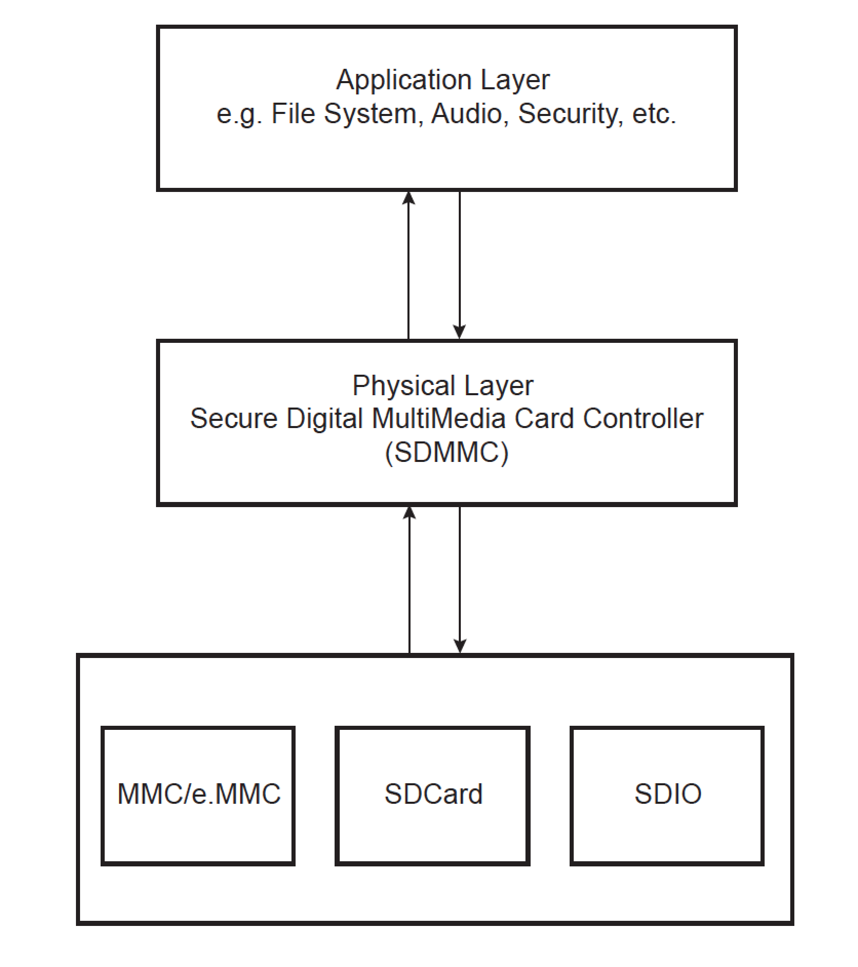 As explained in the [SAMA5D2 Series datasheet](http://ww1.microchip.com/downloads/en/DeviceDoc/60001476A.pdf)
16.4.7.3 SDCard / e.MMC Boot
The SDCard/e.MMC boot requires the Card Detect pin to be connected. If the level on the Card Detect pin is low, SDCard/e.MMC access
is initiated (IOs toggling). If not, no communication with SDCard/e.MMC is performed (no IOs toggling).
So the SDMMCx_CD pin should be used by pulling it down or by connecting it to the specific Card Detect contact of the socket.
**Example 1**
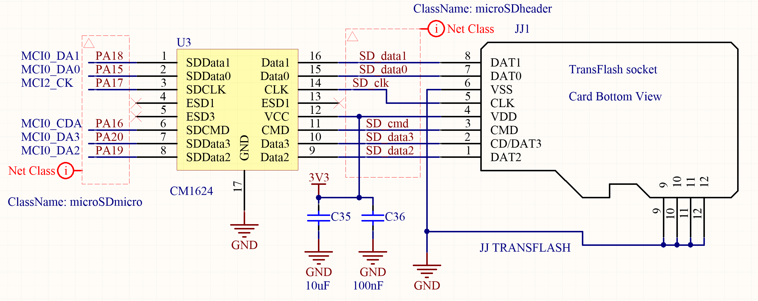
This is an example for a 4-bit connection from SDMMC peripheral to the SD card socket. Data [3..0], Clock and Command signals are used.
The SD card socket is exposed to the external world. Even if not connected with any other device it can suffer by the electrostatic charges accumulated in a human body and discharged to the shield when the fingers touch it. As a usual precaution, some filtering must be applied to avoid both radiated and conducted emissions in order to comply to the EMC specification. Furthermore, the SD card specifications impose pull−up and series impedance matching resistors. Fortunately, as often happens when a device is so commonly spread in mobile equipments, it already exists a chip that implements all of those functions at a time. The CM1624 is a combination EMI filter and line termination device with integrated TVS diodes for use on T-Flash/MicroSD interfaces.
As explained in the [SAMA5D2 Series datasheet](http://ww1.microchip.com/downloads/en/DeviceDoc/60001476A.pdf)
16.4.7.3 SDCard / e.MMC Boot
The SDCard/e.MMC boot requires the Card Detect pin to be connected. If the level on the Card Detect pin is low, SDCard/e.MMC access
is initiated (IOs toggling). If not, no communication with SDCard/e.MMC is performed (no IOs toggling).
So the SDMMCx_CD pin should be used by pulling it down or by connecting it to the specific Card Detect contact of the socket.
**Example 1**
This is an example for a 4-bit connection from SDMMC peripheral to the SD card socket. Data [3..0], Clock and Command signals are used.
The SD card socket is exposed to the external world. Even if not connected with any other device it can suffer by the electrostatic charges accumulated in a human body and discharged to the shield when the fingers touch it. As a usual precaution, some filtering must be applied to avoid both radiated and conducted emissions in order to comply to the EMC specification. Furthermore, the SD card specifications impose pull−up and series impedance matching resistors. Fortunately, as often happens when a device is so commonly spread in mobile equipments, it already exists a chip that implements all of those functions at a time. The CM1624 is a combination EMI filter and line termination device with integrated TVS diodes for use on T-Flash/MicroSD interfaces.
 **Example 2**
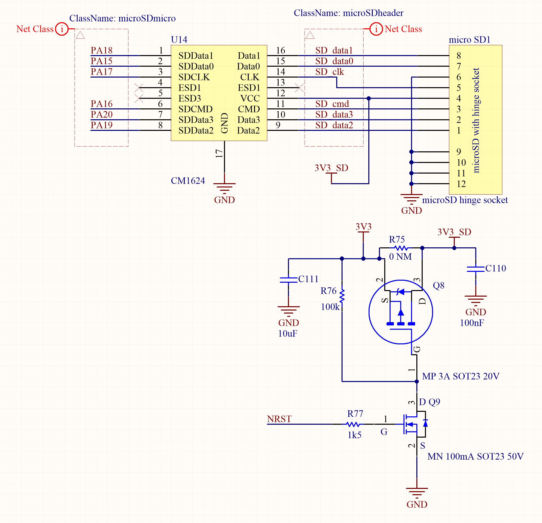
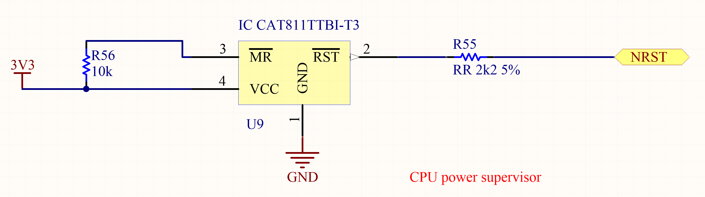
The filesystem stored in the SD card can be corrupted when the power supply voltage is below of a specific threshold. An easy way to protect all the devices, included MCU and SD card, is to tie the reset line for all of them to a Power Supply Supervisor as the CAT811 chip. The reset signal is asserted LOW when the power supply voltage falls below the threshold trip voltage and remains asserted for at least 140 ms after the power supply voltage has risen above the threshold. For the CAT811T version the Nominal Threshold Voltage is 3.08V. The power supply for the SD card can be managed with a circuit like the one depicted below with the supervisor reset control connected to the N mosfet gate.
**Example 2**
The filesystem stored in the SD card can be corrupted when the power supply voltage is below of a specific threshold. An easy way to protect all the devices, included MCU and SD card, is to tie the reset line for all of them to a Power Supply Supervisor as the CAT811 chip. The reset signal is asserted LOW when the power supply voltage falls below the threshold trip voltage and remains asserted for at least 140 ms after the power supply voltage has risen above the threshold. For the CAT811T version the Nominal Threshold Voltage is 3.08V. The power supply for the SD card can be managed with a circuit like the one depicted below with the supervisor reset control connected to the N mosfet gate.
 **Example 3**
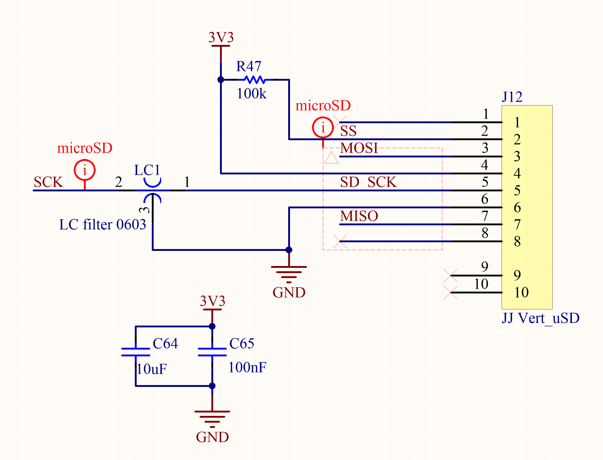
This is an example of an SD card used in SPI mode with the MISO, MOSI, clock and chip select signals connected according to the SD Association specifications. Let's just evidence the filter applied on the clock line to improve the EMC in a very hard environment.
**Example 3**
This is an example of an SD card used in SPI mode with the MISO, MOSI, clock and chip select signals connected according to the SD Association specifications. Let's just evidence the filter applied on the clock line to improve the EMC in a very hard environment.
 ##PCB examples
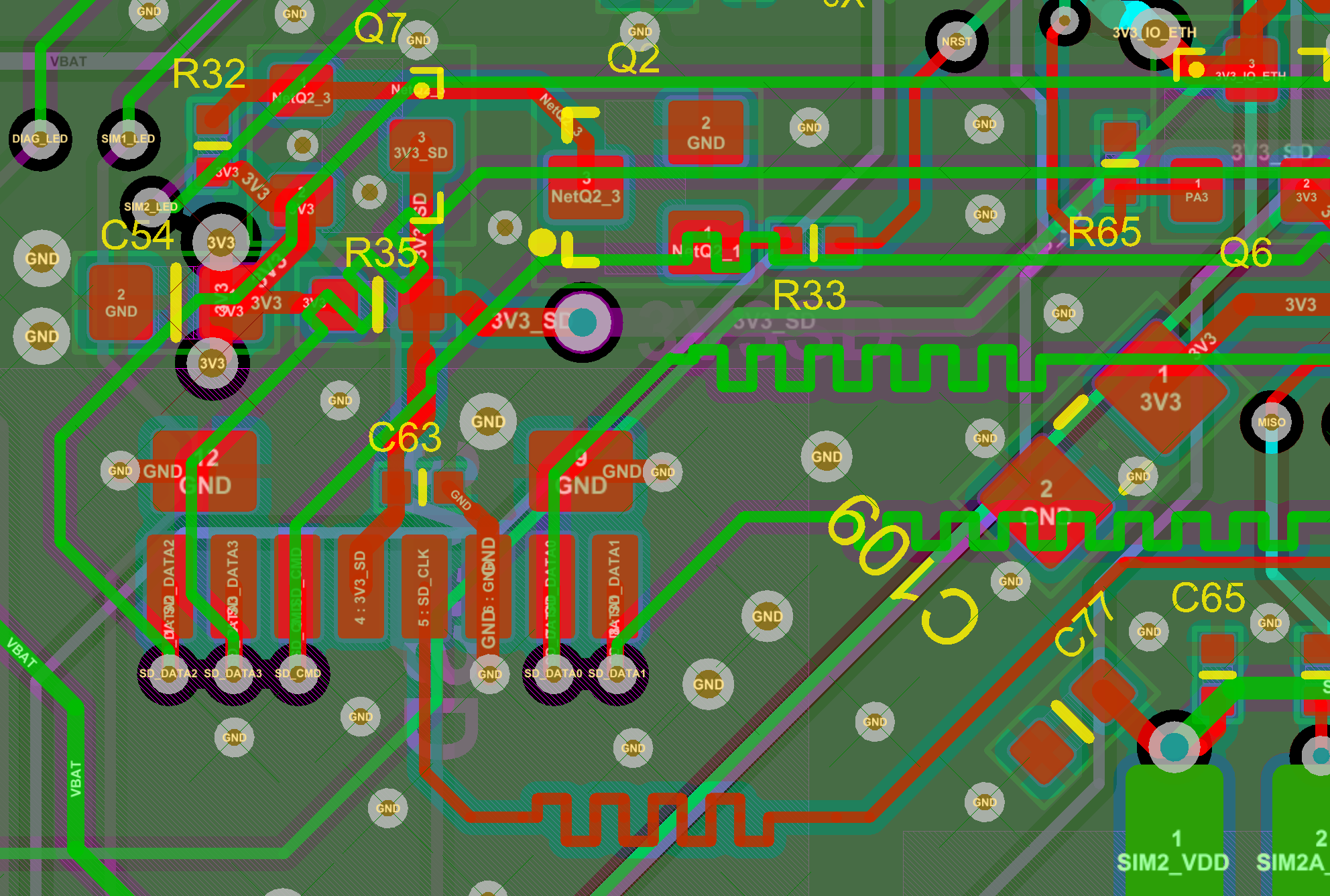
In both 4-bit or SPI mode the tracks carry data and clock signals at an high data rate. In order to avoid glitches, the propagation time must be contemplated, ensuring that all the data are stable at the interface before the clock triggers the reading or writing. The signals path lenght of all data signals must be length matched within some tenths of mm and the clock must be something like 1mm longer. This can be done with the tool already described in [article regarding ethernet](https://www.acmesystems.it/ethernet#matching). To avoid crosstalking those tracks must be kept each with a good ground plane around and below, also connecting the layers with a sufficient number of vias.
The following PCB routing corresponds to the schematics example 1
##PCB examples
In both 4-bit or SPI mode the tracks carry data and clock signals at an high data rate. In order to avoid glitches, the propagation time must be contemplated, ensuring that all the data are stable at the interface before the clock triggers the reading or writing. The signals path lenght of all data signals must be length matched within some tenths of mm and the clock must be something like 1mm longer. This can be done with the tool already described in [article regarding ethernet](https://www.acmesystems.it/ethernet#matching). To avoid crosstalking those tracks must be kept each with a good ground plane around and below, also connecting the layers with a sufficient number of vias.
The following PCB routing corresponds to the schematics example 1
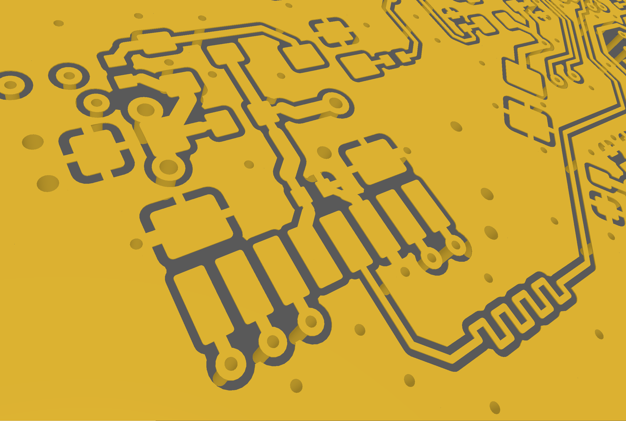
 Resulting in this copper top layer
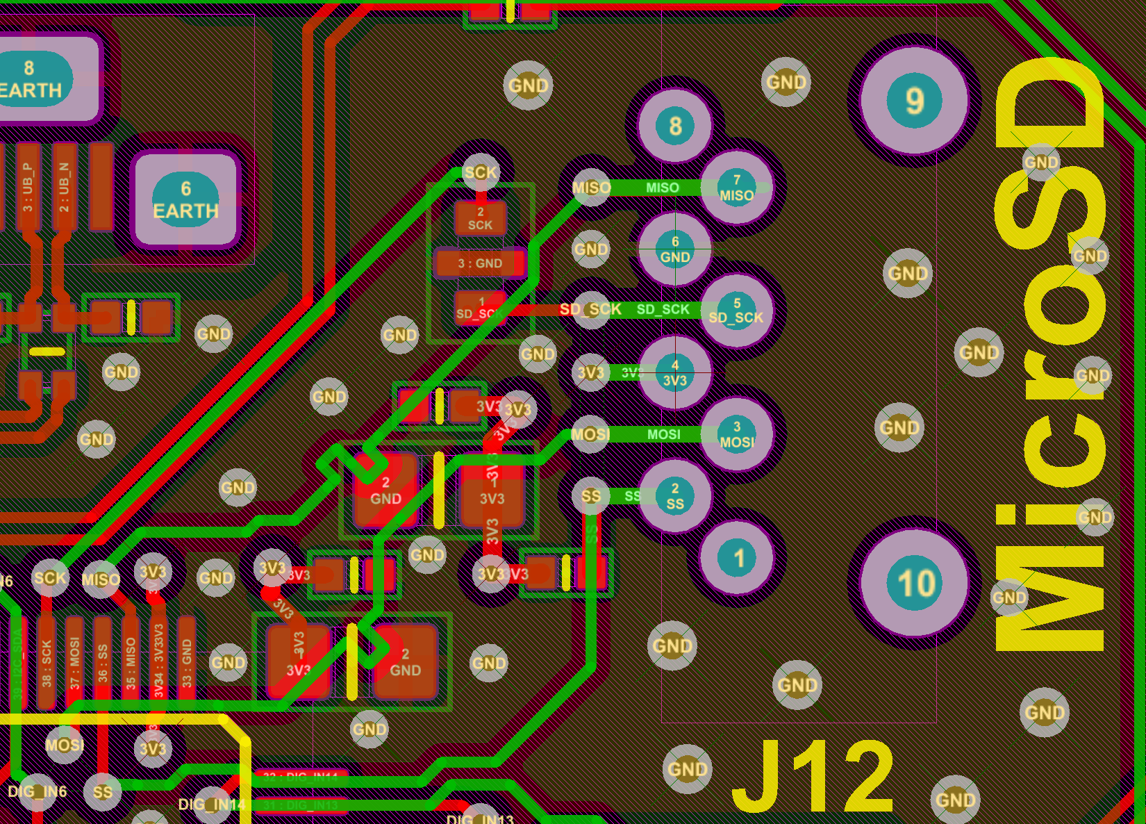
 This PCB rounting corresponds to the schematics example 3 with a vertical type socket.
 ##Connector types
Here some examples, not exhaustive at all, of SD card sockets.
###Push-push
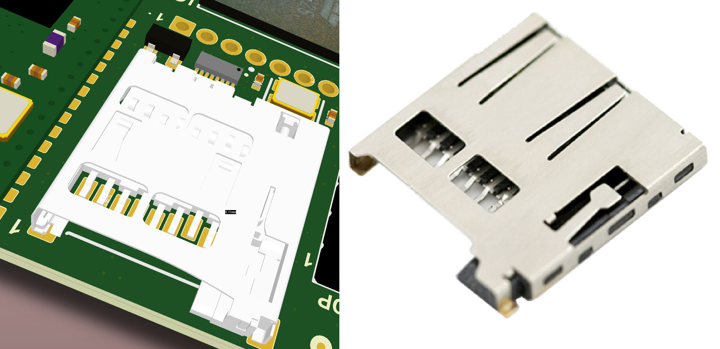
This is the classic push-push socket, very good for frequently changing the card.
Pros:
* The SD card can be easily inserted and ejected by pushing it with little force.
* The card is accesible from outside the box without opening it
* Low profile
Cons:
* The socket must be placed at one edge of the PCB
* More affected by mechanical shocks
##Connector types
Here some examples, not exhaustive at all, of SD card sockets.
###Push-push
This is the classic push-push socket, very good for frequently changing the card.
Pros:
* The SD card can be easily inserted and ejected by pushing it with little force.
* The card is accesible from outside the box without opening it
* Low profile
Cons:
* The socket must be placed at one edge of the PCB
* More affected by mechanical shocks
 @shop='MSD-HOLDER-1'
###Hinge socket
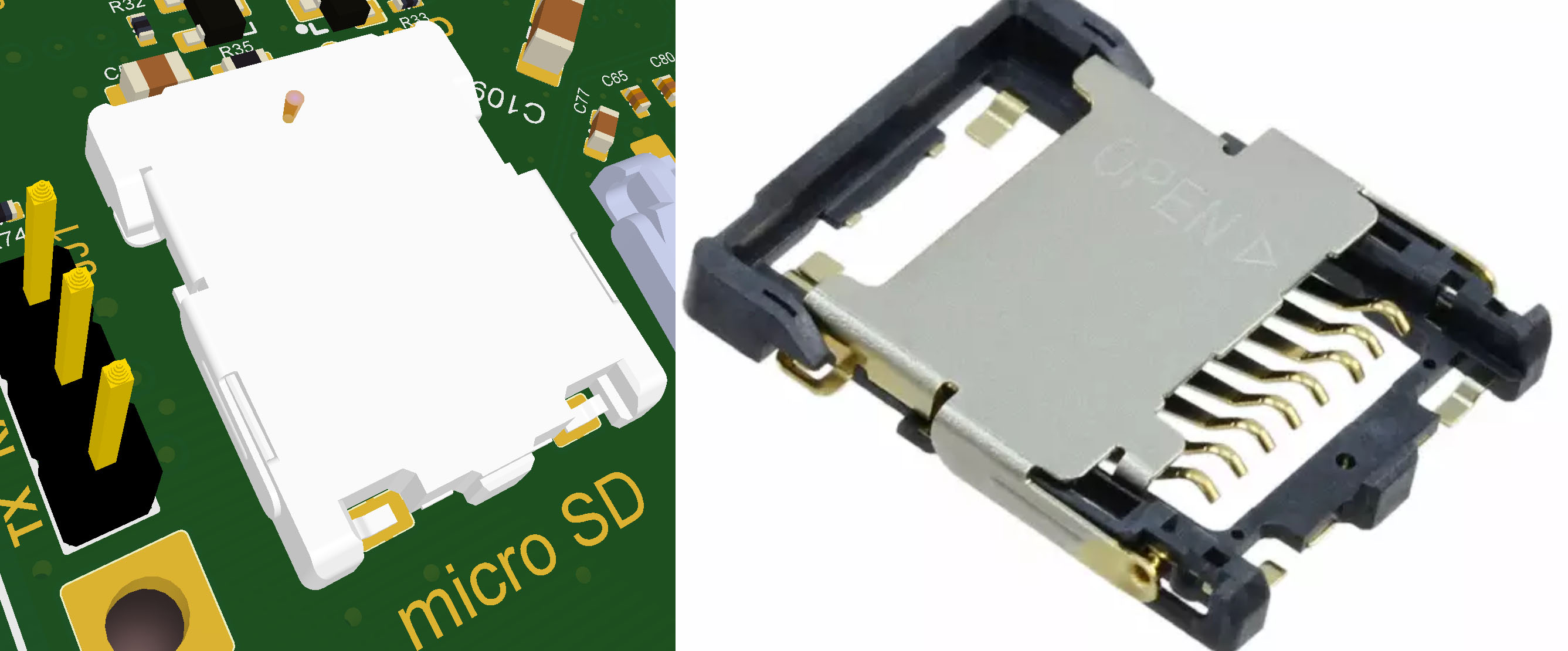
The hinge socket needs to be unlocked to extract the SD card. More suitable for shock resistant installation with rare removal.
Pros:
* Very low profile
* The socket can be placed anywhere on the PCB
* Very reliable connection even in hard environment
Cons:
* It requires access to the inside of the box
* A little bit more complicated insertion and extraction
@shop='MSD-HOLDER-1'
###Hinge socket
The hinge socket needs to be unlocked to extract the SD card. More suitable for shock resistant installation with rare removal.
Pros:
* Very low profile
* The socket can be placed anywhere on the PCB
* Very reliable connection even in hard environment
Cons:
* It requires access to the inside of the box
* A little bit more complicated insertion and extraction
 @shop='MSD-HOLDER-2'
###Vertical push-pull
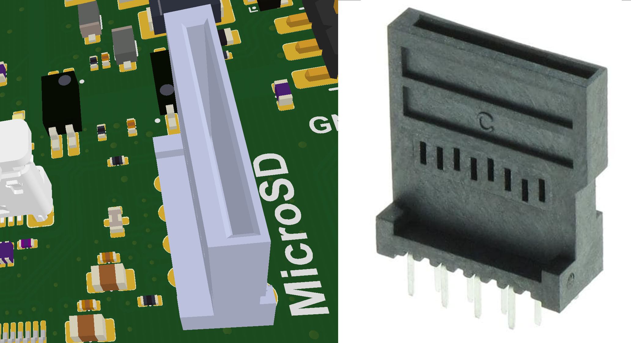
The vertical, push-pull socket has a very small footprint on the PCB. It's perfect for managing the card from the top side when no other side is accessible.
Pros:
* Small impact on the PCB
* Accessible from the top of the box
Cons:
* Not suggested for mobile equipments due to some lack of reliable locking mechanism
* It requires access to the inside of the box
@shop='MSD-HOLDER-2'
###Vertical push-pull
The vertical, push-pull socket has a very small footprint on the PCB. It's perfect for managing the card from the top side when no other side is accessible.
Pros:
* Small impact on the PCB
* Accessible from the top of the box
Cons:
* Not suggested for mobile equipments due to some lack of reliable locking mechanism
* It requires access to the inside of the box
 @shop='MSD-HOLDER-3'
##Related links
* [Roadrunner SD card controllers pinout **(PRELIMINARY)**](./RR-SDcard.png)
* [Microchip SAMA5D27 MCU datasheet](http://ww1.microchip.com/downloads/en/DeviceDoc/60001476A.pdf)
* [CM1624 EMI Filter for MicroSD Interfaces](http://www.onsemi.com/pub/Collateral/CM1624-D.PDF)
* [CAT811 Power Supply Supervisor](http://www.mouser.com/ds/2/308/on%20semiconductor_cat811-d-549254.pdf)
* [Wikipedia Secure Digital](https://en.wikipedia.org/wiki/Secure_Digital)
* [SD Association](https://www.sdcard.org/)
* [SD card semplified specifications](https://www.sdcard.org/downloads/pls/)
@include='bio_guiott'
@shop='MSD-HOLDER-3'
##Related links
* [Roadrunner SD card controllers pinout **(PRELIMINARY)**](./RR-SDcard.png)
* [Microchip SAMA5D27 MCU datasheet](http://ww1.microchip.com/downloads/en/DeviceDoc/60001476A.pdf)
* [CM1624 EMI Filter for MicroSD Interfaces](http://www.onsemi.com/pub/Collateral/CM1624-D.PDF)
* [CAT811 Power Supply Supervisor](http://www.mouser.com/ds/2/308/on%20semiconductor_cat811-d-549254.pdf)
* [Wikipedia Secure Digital](https://en.wikipedia.org/wiki/Secure_Digital)
* [SD Association](https://www.sdcard.org/)
* [SD card semplified specifications](https://www.sdcard.org/downloads/pls/)
@include='bio_guiott'