# How to design the PWM circuitry
The **P**ulse **W**idth **M**odulation is a method to close up the digital world of an MCU with the analog real world with the maximum efficiency. This article will depict some hardware interfaces and techniques to connect the TTL levels of the Roadrunner MCU with the high power devices. Likewise the communication peripherals, we can talk about the *physical layer* for a PWM module.
##Introduction
The [**Roadrunner SOM**](https://www.acmesystems.it/roadrunner) uses a Microchip SAMA5D27 MCU. As described on [SAMA5D2 Series datasheet](http://ww1.microchip.com/downloads/en/DeviceDoc/60001476A.pdf) it can make available the following PWM peripherals:
* Two 3-channel 32-bit Timer/Counters (TC), supporting basic PWM modes
* One full-featured 4-channel 16-bit Pulse Width Modulation (PWM) controller
Most of the applications can be realized also with the basic PWM peripheral. For a more sophisticated driving, e.g. a fine control of a **B**rush**L**ess **DC** motor, it may require the further features of an advanced PWM:
* Each channel controls two complementary square output waveforms.
* Characteristics of the output waveforms such as period, duty-cycle, polarity and dead-times are configured through the user interface.
* External triggers can be managed to allow output pulses to be modified in real time.
* All channels integrate a double buffering system in order to prevent any unexpected output waveform while modifying the period, the spread spectrum, the duty-cycle or the dead-times.
* Channels can be linked together as synchronous channels to be able to update their duty-cycle or dead-times at the same time.
* The update of duty-cycles of synchronous channels can be performed by the DMA Controller channel, which offers buffer transfer without processor Intervention.
* The PWM includes a spread-spectrum counter to allow a constantly varying period (only for Channel 0). This counter may be useful to
minimize electromagnetic interference or to reduce the acoustic noise of a PWM driven motor.
* The PWM provides 1 independent comparison unit capable of comparing a programmed value to the counter of the synchronous channels
(counter of channel 0). These comparisons are intended to generate software interrupts, to trigger pulses on the 2 independent events
lines (in order to synchronize ADC conversions with a lot of flexibility independently of the PWM outputs) and to trigger DMA Controller
transfer requests.
* PWM outputs can be overridden synchronously or asynchronously to their channel counter.
* The PWM provides a fault protection mechanism with 6 fault inputs, capable to detect a fault condition and to override the PWM outputs
asynchronously (outputs forced to ‘0’, ‘1’ or Hi-Z).
* For safety usage, some configuration registers are write-protected.
##PWM peripherals
Let's take a deeper look at the different modules as explained in the datasheet.
###Chapter 54. Timer Counter (TC)
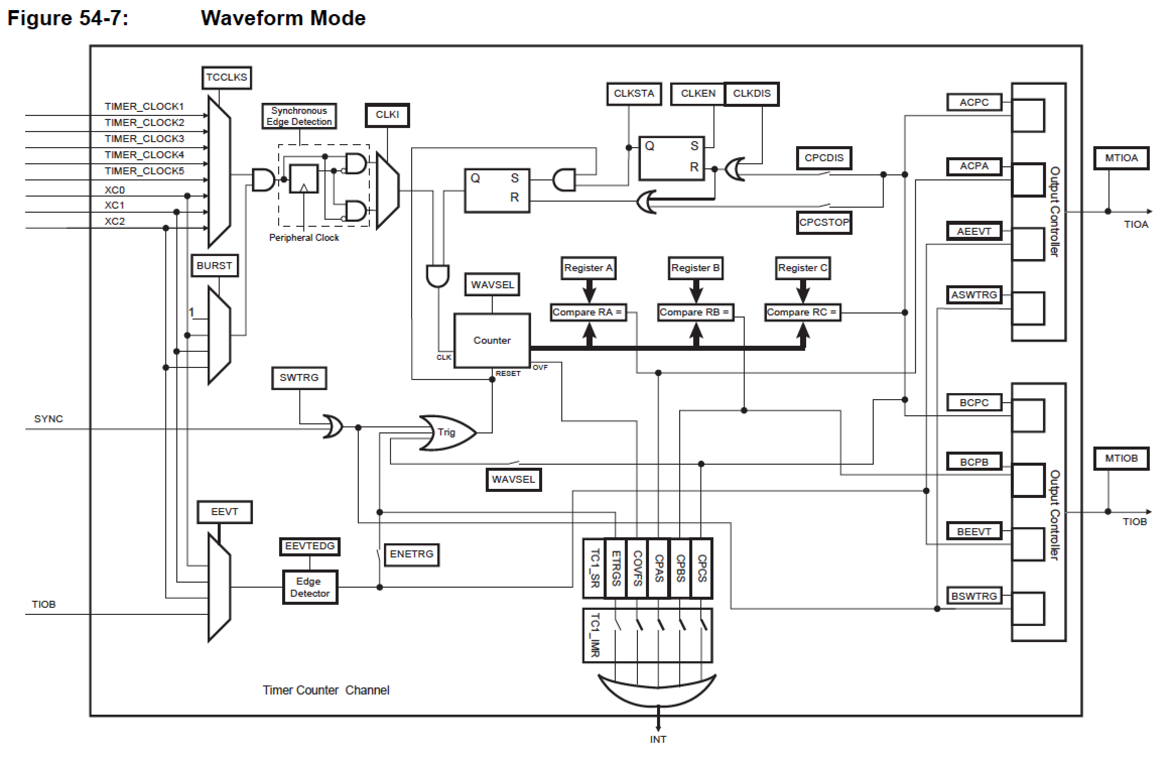
In Waveform mode, the TC channel generates one or two PWM signals with the same frequency and independently programmable duty
cycles, or generates different types of one-shot or repetitive pulses.
In this mode, TIOAx is configured as an output and TIOBx is defined as an output if it is not used as an external event (TC_CMR.EEVT).
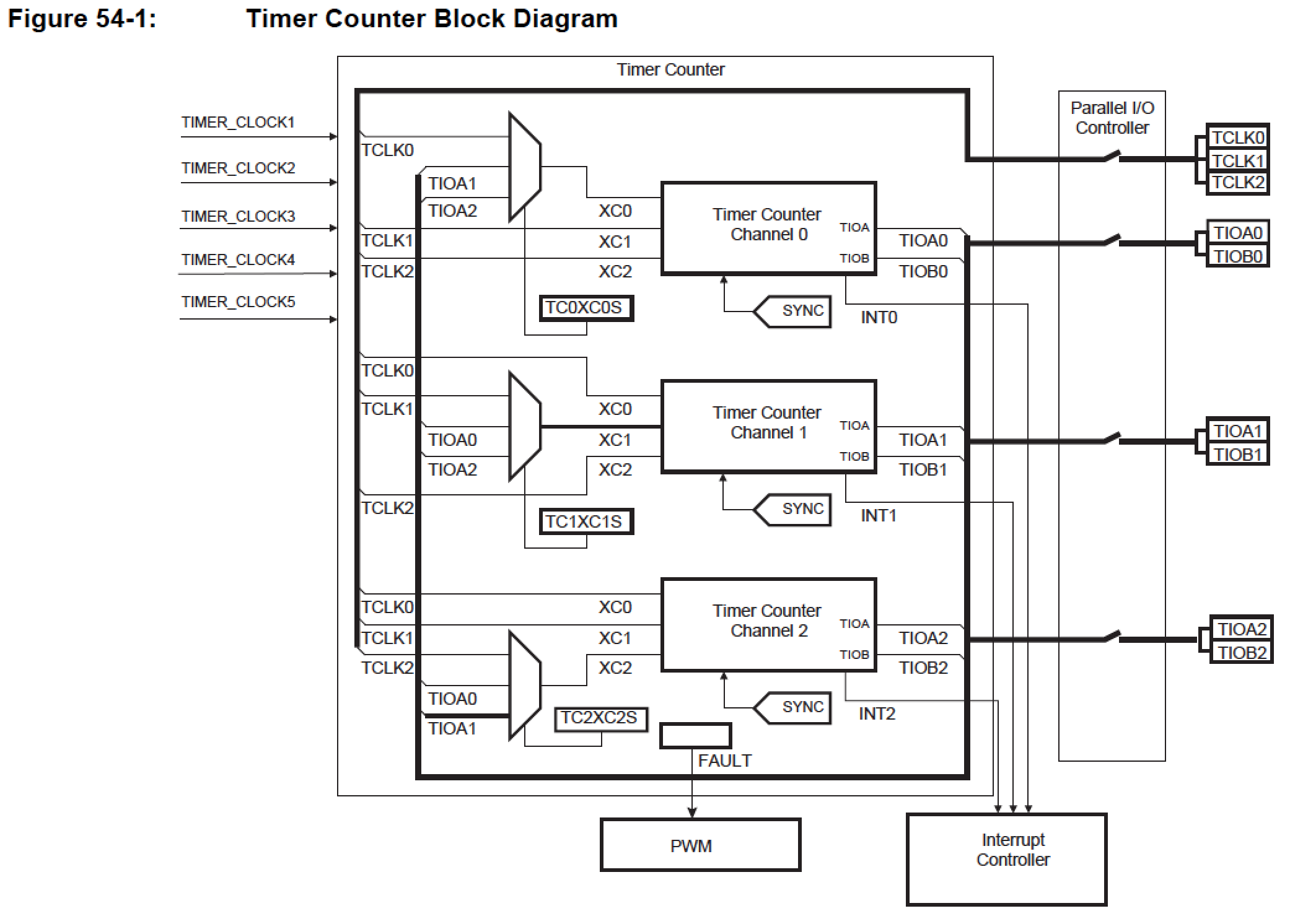 Figure 54-7 shows the configuration of the TC channel when programmed in Waveform operating mode.
 ###Chapter 56. Pulse Width Modulation Controller (PWM)
56.1 Description
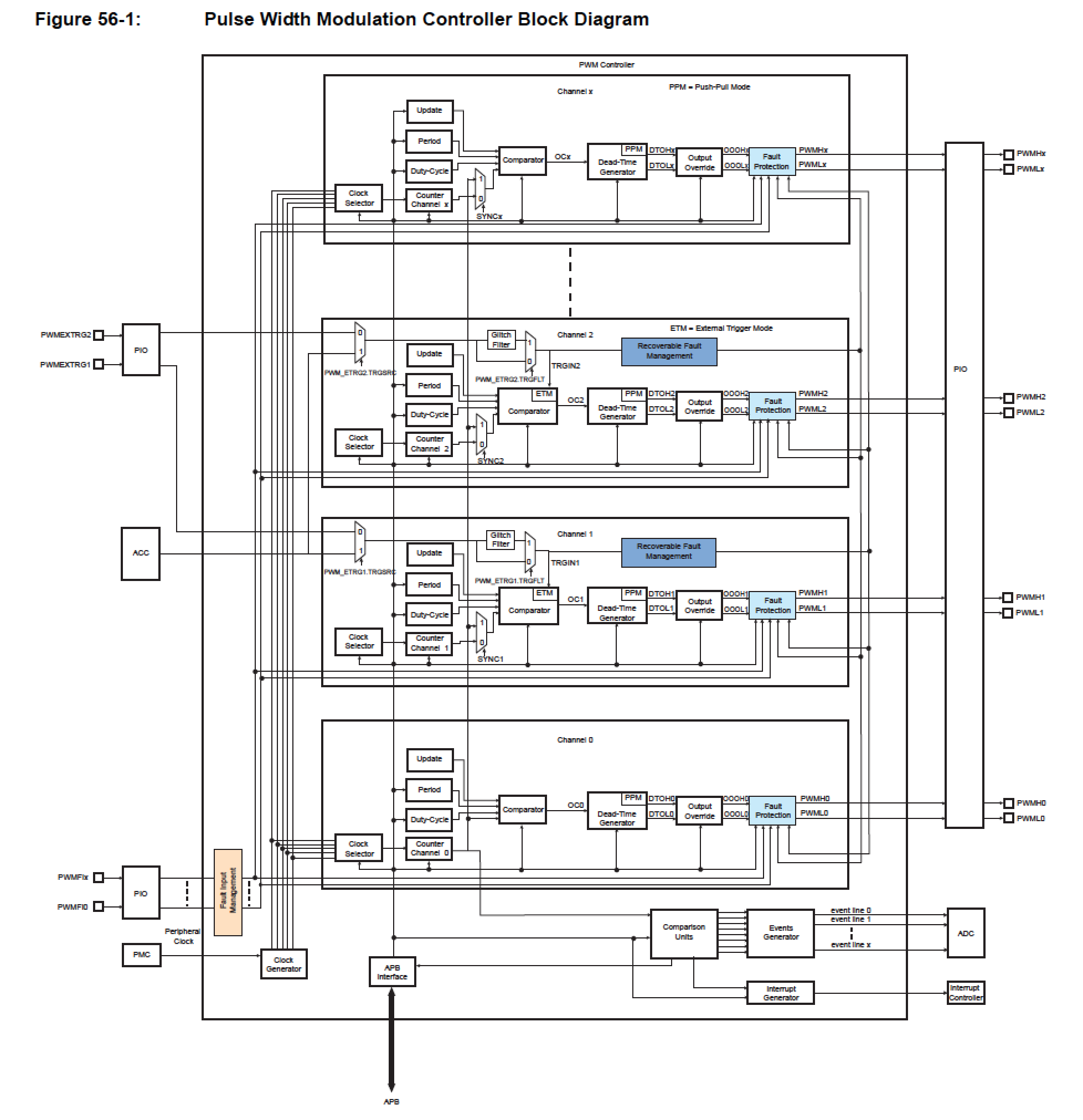
The Pulse Width Modulation Controller (PWM) generates output pulses on 4 channels independently according to parameters defined per
channel. Each channel controls two complementary square output waveforms. Characteristics of the output waveforms such as period,
duty-cycle, polarity and dead-times (also called dead-bands or non-overlapping times) are configured through the user interface. Each
channel selects and uses one of the clocks provided by the clock generator.
###Chapter 56. Pulse Width Modulation Controller (PWM)
56.1 Description
The Pulse Width Modulation Controller (PWM) generates output pulses on 4 channels independently according to parameters defined per
channel. Each channel controls two complementary square output waveforms. Characteristics of the output waveforms such as period,
duty-cycle, polarity and dead-times (also called dead-bands or non-overlapping times) are configured through the user interface. Each
channel selects and uses one of the clocks provided by the clock generator.
 ##Applications
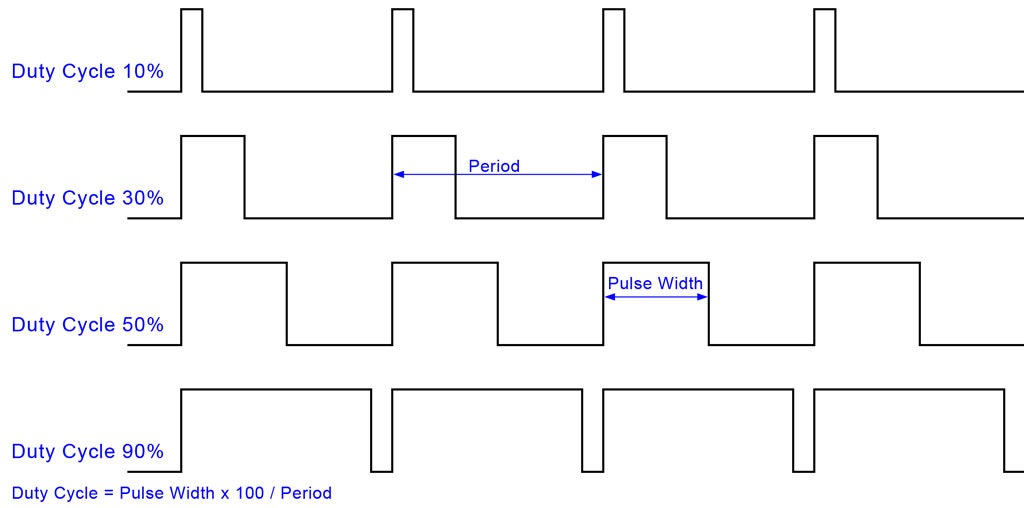
Let's summarize the common lexicon about PWM
##Applications
Let's summarize the common lexicon about PWM
 If just a low current, slow changing analog signal is required, we can modulate the power supply and integrate it with an RC network. If this low-pass filter has a cutoff frequency low enough for the chosen PWM period, the ripple over the analog signal is low.
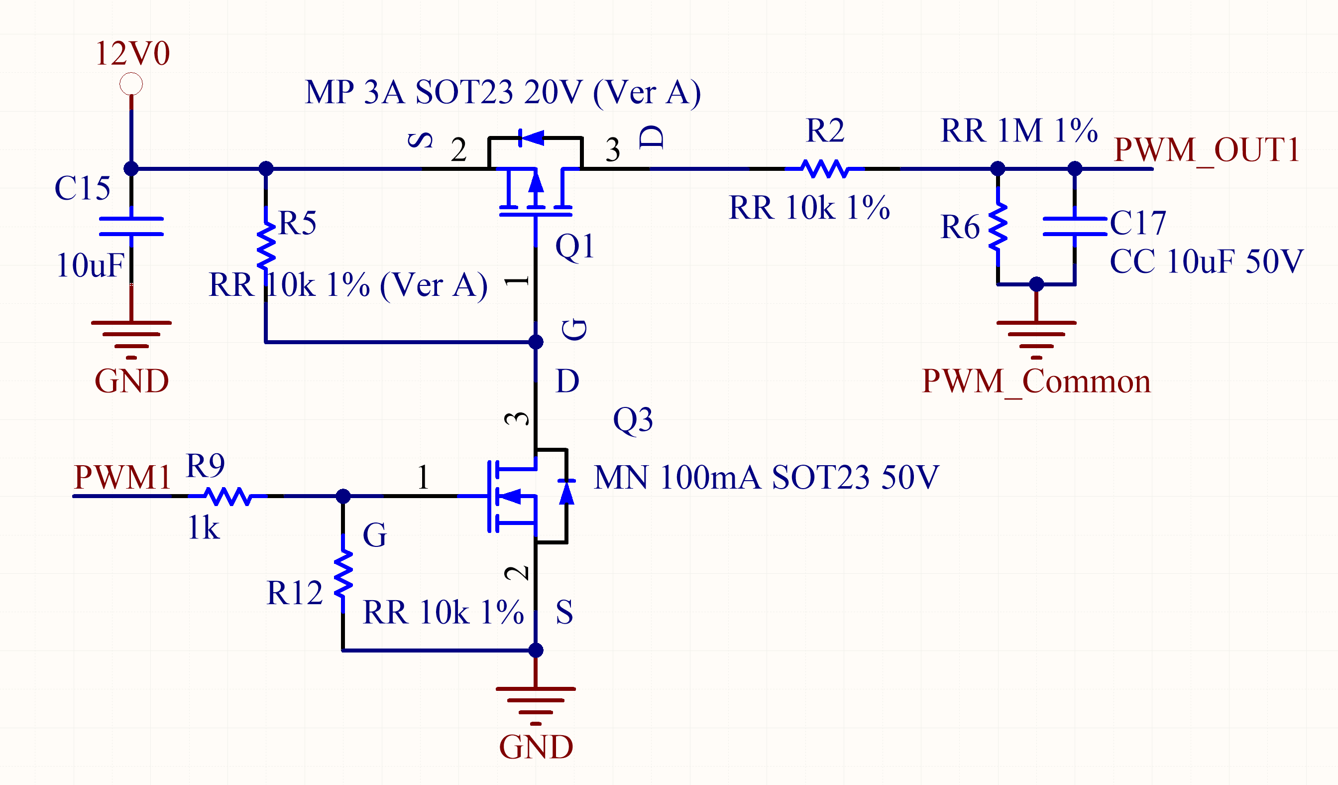 To control a light load (for example the brightness of a LED) a circuit with simple N mosfet can be used. If the switching frequency is high enough, no integrating filter is needed to avoid flickering.
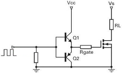
 If the load is heavier, like lamps, heaters, etc. to supply the current required by the power mosfet gate we must use a specific driver. This charge pump provides enough energy to quickly charge the equivalent capacitor of the mosfet gate, allowing a very sharp edge switching and minimizing the power loss on commutation.
A simplified schematic of a mosfet gate driver
If the load is heavier, like lamps, heaters, etc. to supply the current required by the power mosfet gate we must use a specific driver. This charge pump provides enough energy to quickly charge the equivalent capacitor of the mosfet gate, allowing a very sharp edge switching and minimizing the power loss on commutation.
A simplified schematic of a mosfet gate driver
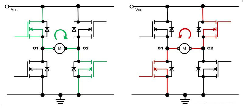
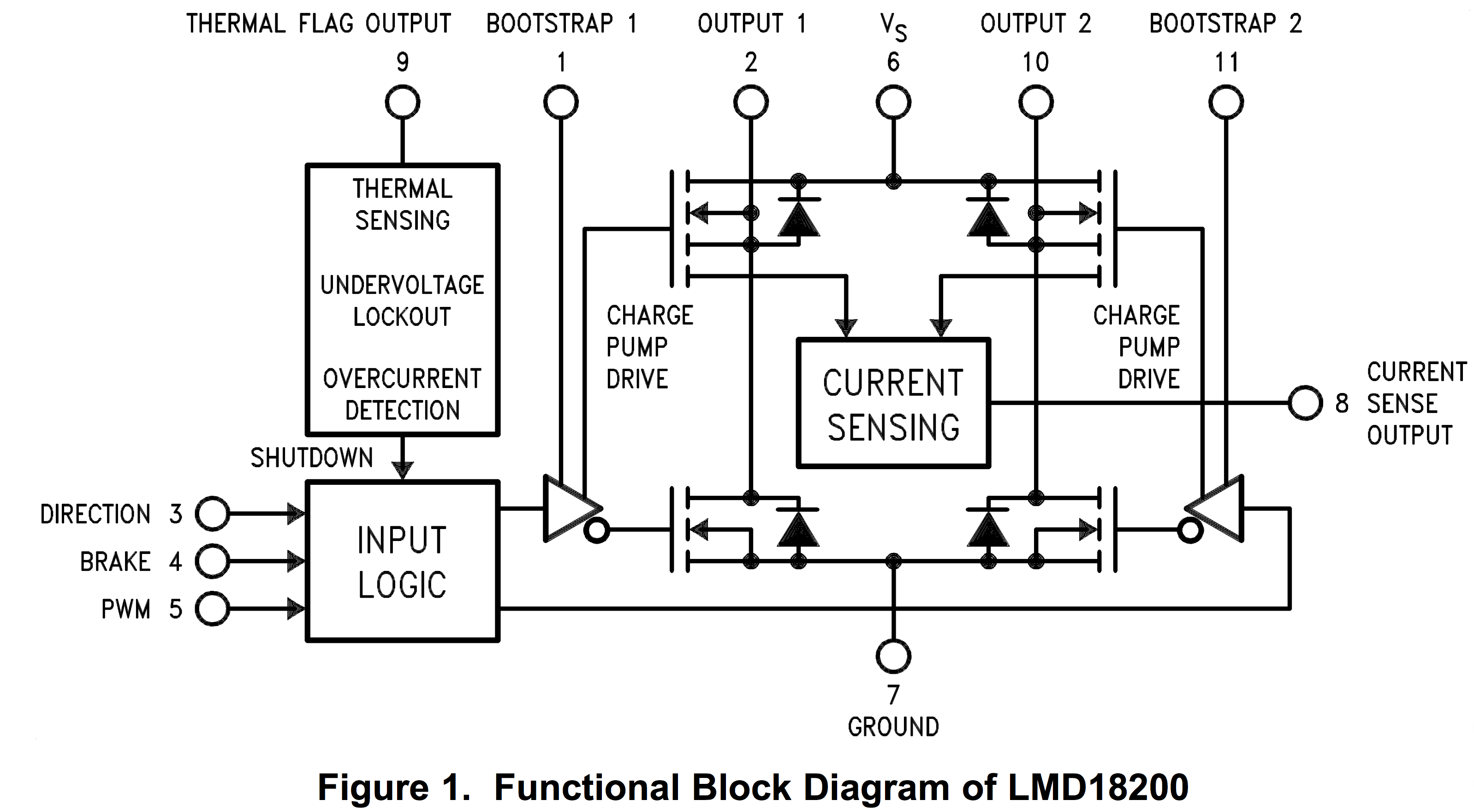
 For a full control of a brushed motor, i.e. speed and direction, it requires four power mosfets in an H-bridge configuration. Driving alternatively the opposite couples of mosfets the flowing current can be modulated in both directions.
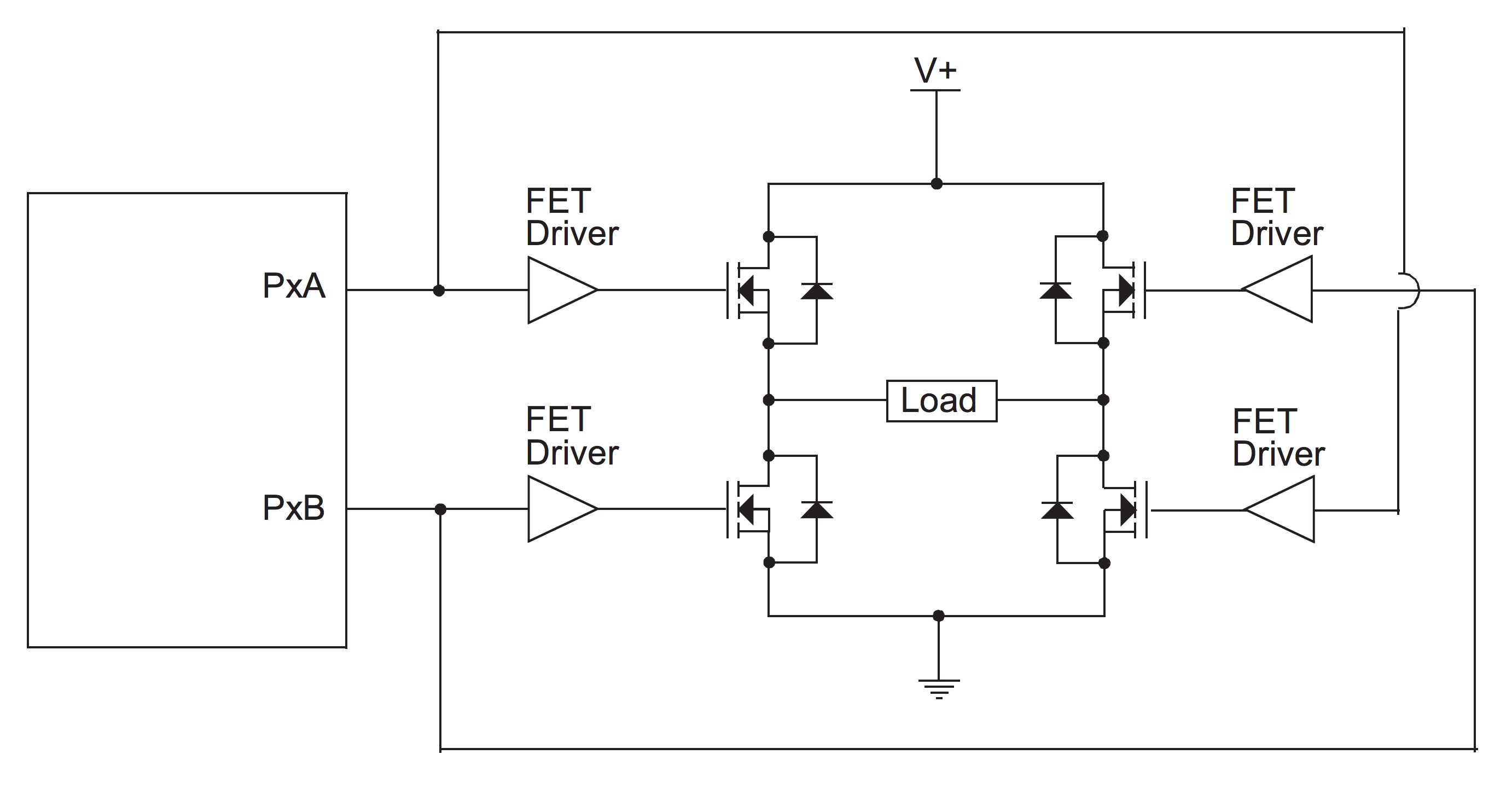
 The gate drivers of the symmetric mosfets are coupled to allow a complementary driving, i.e. with two PWM signals in opposite phase. Alternatively, if no complementary PWM is available, a NOT gate can be used to invert one of the signals.
 There are plenty of dedicated H-bridges chips that include drivers, power mosfets, control logic and other useful features. An example of them is the [Texas Instruments LMD18200](http://www.ti.com/lit/ds/symlink/lmd18200.pdf)
 ##LAP vs. S/M
To control a motor the H-bridge can be driven in **L**ocked **A**nti**P**hase or **S**ign/**M**agnitude mode. For a simple direction control the S/M mode is good enough. To accurately control the speed and/or position as on driving a moving vehicle with a closed loop control, the LAP mode is mandatory.
Let's explain with a graph the different conditions under which a motor may be subjected in usual driving.
##LAP vs. S/M
To control a motor the H-bridge can be driven in **L**ocked **A**nti**P**hase or **S**ign/**M**agnitude mode. For a simple direction control the S/M mode is good enough. To accurately control the speed and/or position as on driving a moving vehicle with a closed loop control, the LAP mode is mandatory.
Let's explain with a graph the different conditions under which a motor may be subjected in usual driving.
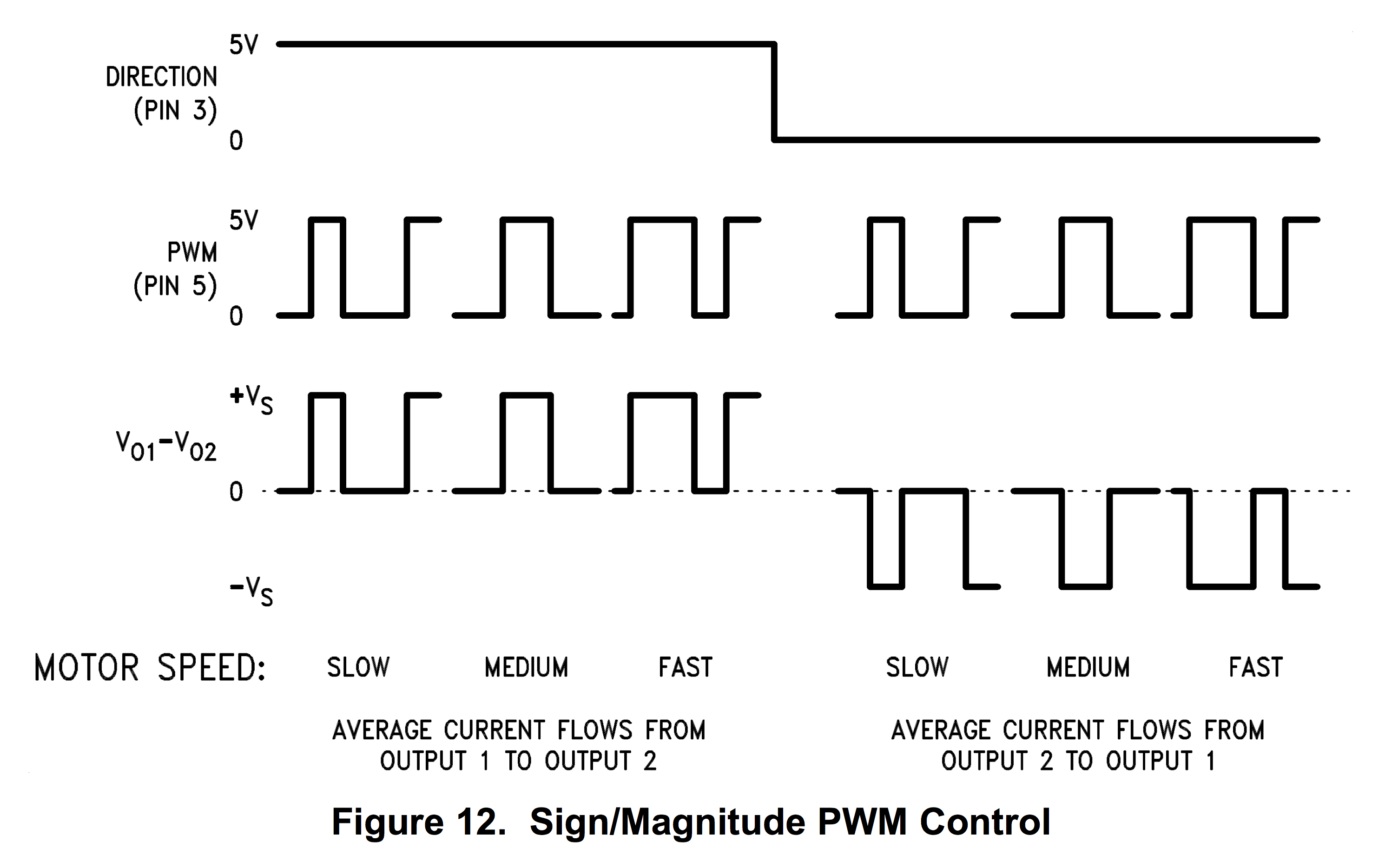
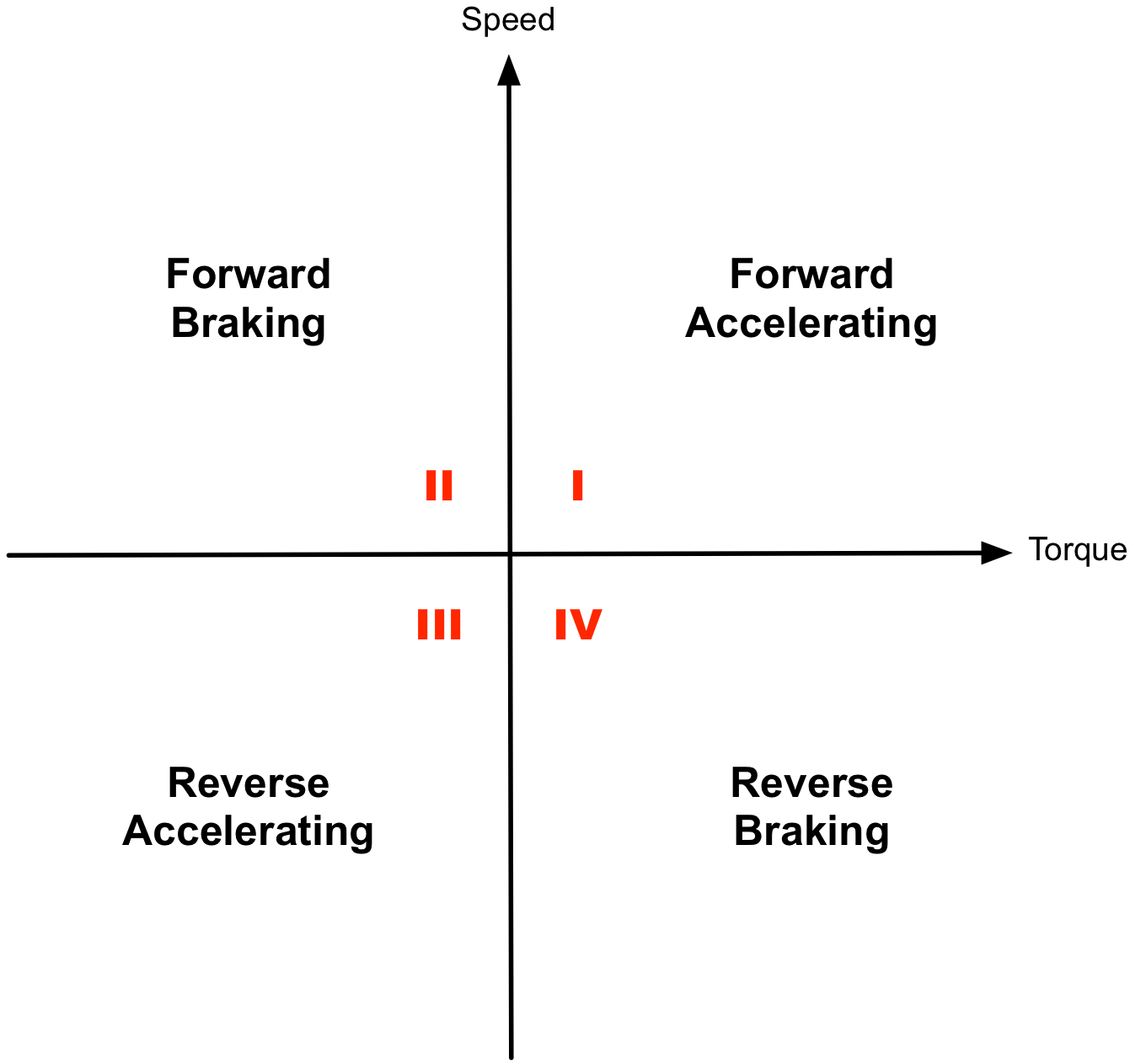 The S/M is the so-called two-quadrant mode: I and III.
Increasing the current through the coils increases the torque and speed increases as a consequence. Slowing down the motor, however, is achieved only by reducing the current through coil and the motor slows down through the natural friction and load inertia. The two-quadrant mode of operation does not provide strong control over the motor operation.
A single PWM is applied to a couple of opposite mosfets and another signal is used to decide the rotating direction. When the duty-cycle falls to zero, the mosfets are all open and the motor is in free-running mode.
The S/M is the so-called two-quadrant mode: I and III.
Increasing the current through the coils increases the torque and speed increases as a consequence. Slowing down the motor, however, is achieved only by reducing the current through coil and the motor slows down through the natural friction and load inertia. The two-quadrant mode of operation does not provide strong control over the motor operation.
A single PWM is applied to a couple of opposite mosfets and another signal is used to decide the rotating direction. When the duty-cycle falls to zero, the mosfets are all open and the motor is in free-running mode.
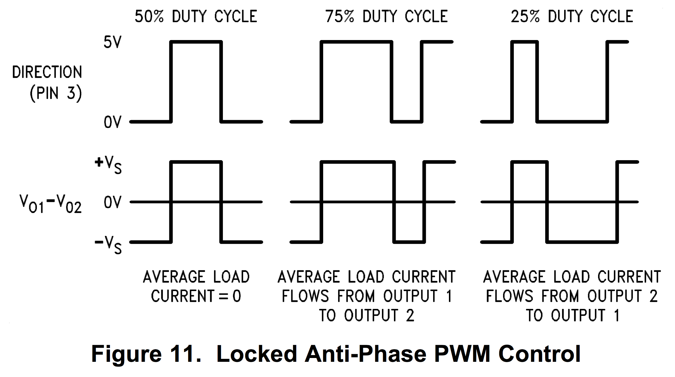
 With LAP mode the motor is under control in all of the four quadrants. The torque is actively used also to apply brakes when we want to slow down the motor. The motor is generating power instead of consuming it. In this way there is full control on the motor speed both when accelerating and decelerating in forward or reverse direction.
Here we use two complentary PWM signals (generated by the MCU or obtained with an external control logic) to alternatively switch the two sides of the H-bridge. A duty-cycle of 50% carries zero average current. From 50 to 100% we are in quadrant I and II, with active braking. From 50% down to 0 we are in quadrant III and IV, with full control too.
In order to work correctly in LAP mode, with the maximum efficiency and no vibration noise, the PWM frequency must be carefully chosen. This depends upon electrical and mechanical time constant of the motor and can also be defined experimentally. The filter capacitors usually applied to the motor brushes to reduce EMI, and sometime installed inside the motor by the producer, are not compatible at all with this mode. They can degrade a lot the performances causing a dangerous overheating of the H-bridge mosfets.
With LAP mode the motor is under control in all of the four quadrants. The torque is actively used also to apply brakes when we want to slow down the motor. The motor is generating power instead of consuming it. In this way there is full control on the motor speed both when accelerating and decelerating in forward or reverse direction.
Here we use two complentary PWM signals (generated by the MCU or obtained with an external control logic) to alternatively switch the two sides of the H-bridge. A duty-cycle of 50% carries zero average current. From 50 to 100% we are in quadrant I and II, with active braking. From 50% down to 0 we are in quadrant III and IV, with full control too.
In order to work correctly in LAP mode, with the maximum efficiency and no vibration noise, the PWM frequency must be carefully chosen. This depends upon electrical and mechanical time constant of the motor and can also be defined experimentally. The filter capacitors usually applied to the motor brushes to reduce EMI, and sometime installed inside the motor by the producer, are not compatible at all with this mode. They can degrade a lot the performances causing a dangerous overheating of the H-bridge mosfets.
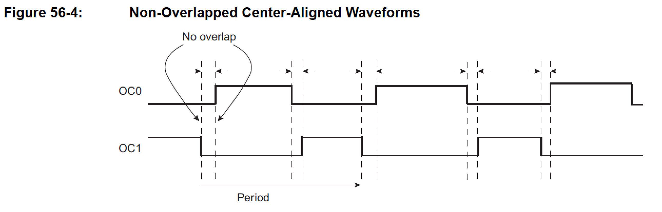
 In order to avoid possible short circuits due to a slight ON or OFF delay of the complementary mosfets, a *dead band* may be used with the advanced PWM controller in complementary mode. This avoids overlapping in the switching phase of the H-bridge driving. The logic control in the advanced H-bridges chips are already fitted with the correct dead-times.
 ##Related links
* [Roadrunner USB pinout **(PRELIMINARY)**](./ROADRUNNER-pinout.png)
* [SAMA5D2 Series datasheet](http://ww1.microchip.com/downloads/en/DeviceDoc/60001476A.pdf)
* [Texas Instruments LMD18200](http://www.ti.com/lit/ds/symlink/lmd18200.pdf)
@include='bio_guiott'
##Related links
* [Roadrunner USB pinout **(PRELIMINARY)**](./ROADRUNNER-pinout.png)
* [SAMA5D2 Series datasheet](http://ww1.microchip.com/downloads/en/DeviceDoc/60001476A.pdf)
* [Texas Instruments LMD18200](http://www.ti.com/lit/ds/symlink/lmd18200.pdf)
@include='bio_guiott'