# How to design the serial circuitry
The serial bus is one of the first communication systems in the computer era. Despite its venerable age, it's still well alive and used for the great simplicity in both hardware and software management. Virtually all the microcontrollers have this kind of peripherals. This article describes some different physical layer interfaces of those peripherals.
##Introduction
The [**Roadrunner SOM's**](https://www.acmesystems.it/roadrunner) SAMA5D27 MCU has the following serial peripherals that can be used:
* Five simple UARTs
* Five FLEXCOMs, configurable as full-featured USART, other than SPI and TWI
for a total of up to ten possible separated serial communications.
The simple UART ports use just RX and TX for communication
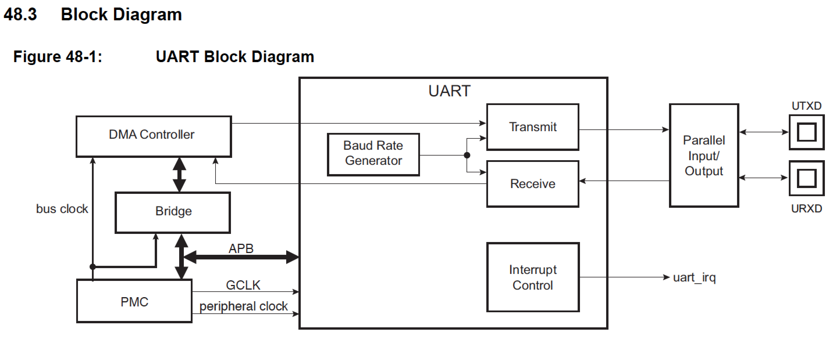 *Table 48-1: UART Pin Description*
| Pin Name |Description | Type |
|----------|--------------|-------|
| URXD UART| Receive Data |Input |
| UTXD UART| Transmit Data| Output|
With the FLEXCOM also the hardware RTS-CTS handshaking may be used optionally
*Table 48-1: UART Pin Description*
| Pin Name |Description | Type |
|----------|--------------|-------|
| URXD UART| Receive Data |Input |
| UTXD UART| Transmit Data| Output|
With the FLEXCOM also the hardware RTS-CTS handshaking may be used optionally
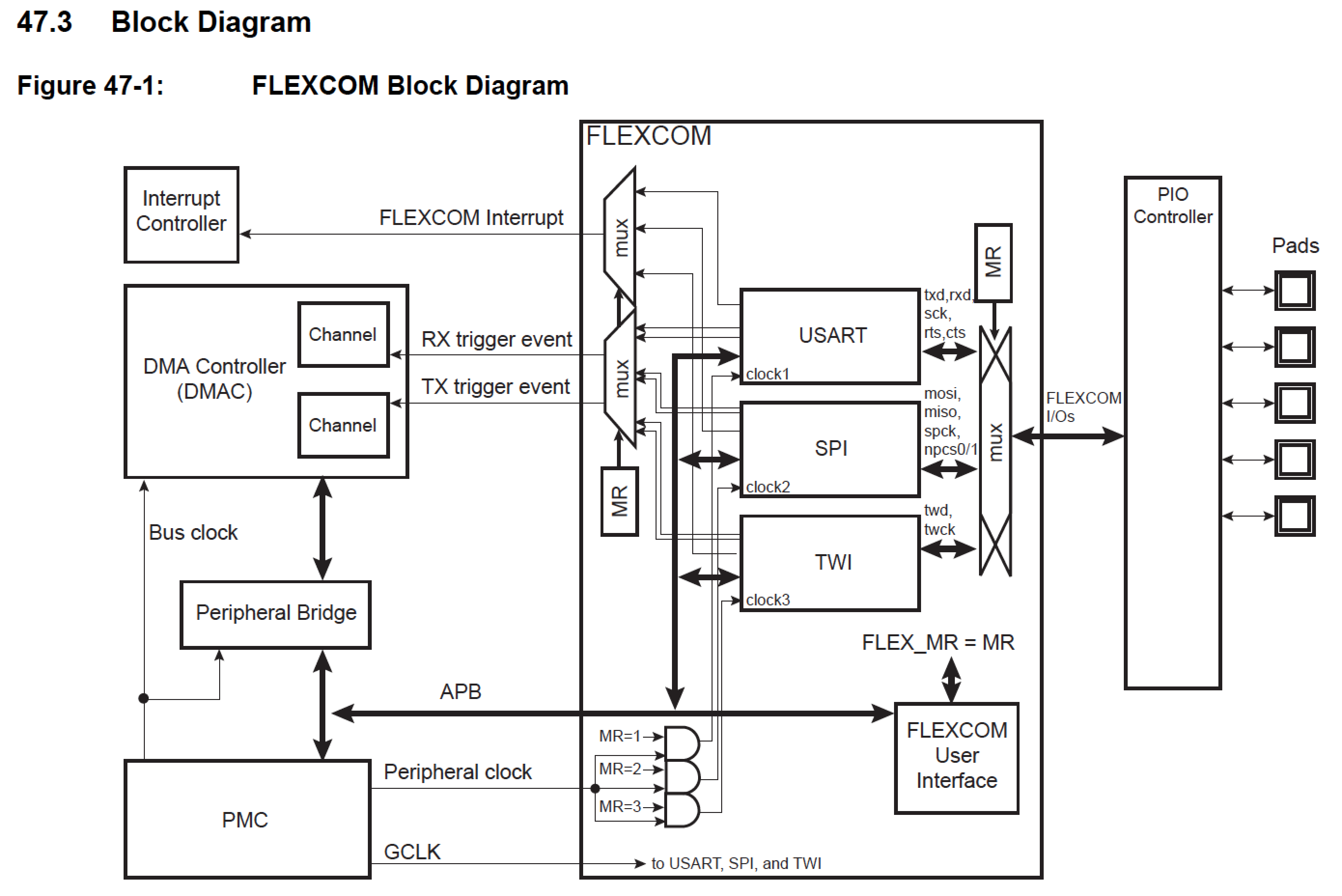 *Table 47-2: I/O Lines Description*
|Name | Description |
|------------|-------------|
|FLEXCOM_IO0 | TXD |
|FLEXCOM_IO1 | RXD |
|FLEXCOM_IO2 | SCK |
|FLEXCOM_IO3 | CTS |
|FLEXCOM_IO4 | RTS |
___
##Serial TTL
The simplest way is the direct connection to the TX-RX pins. This system is often used for the console output and debugging, but it may be used to directly connect more MCUs or the MCU with simple devices. Without any line driver or protection systems it's suggested to use this mode just for debugging in a supervised environment or to connect devices within the same system. Pay attention to the I/O voltage level of devices with different power supply, not all of them are voltage tolerant.
*Table 47-2: I/O Lines Description*
|Name | Description |
|------------|-------------|
|FLEXCOM_IO0 | TXD |
|FLEXCOM_IO1 | RXD |
|FLEXCOM_IO2 | SCK |
|FLEXCOM_IO3 | CTS |
|FLEXCOM_IO4 | RTS |
___
##Serial TTL
The simplest way is the direct connection to the TX-RX pins. This system is often used for the console output and debugging, but it may be used to directly connect more MCUs or the MCU with simple devices. Without any line driver or protection systems it's suggested to use this mode just for debugging in a supervised environment or to connect devices within the same system. Pay attention to the I/O voltage level of devices with different power supply, not all of them are voltage tolerant.
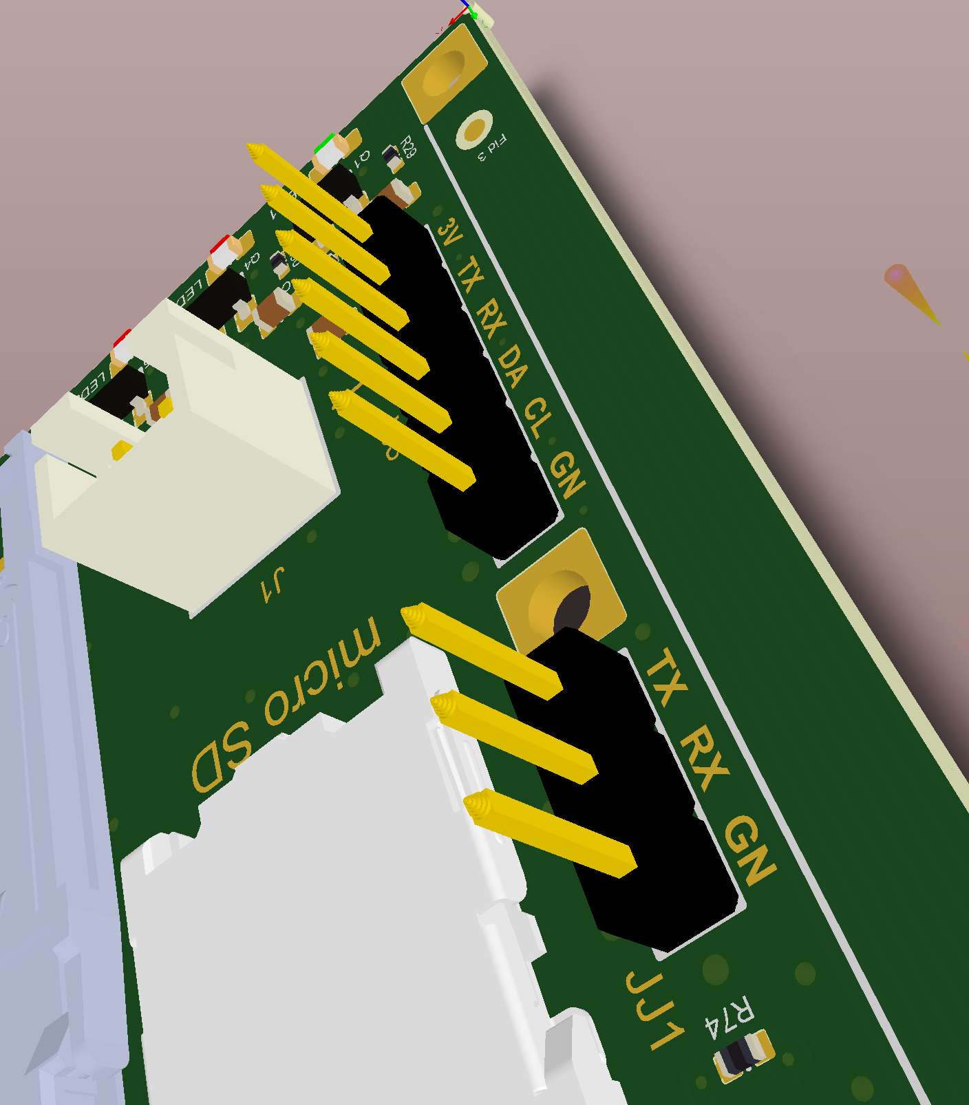 The TTL communication can be achieved also with a computer, interfacing it through an [USB to serial converter](https://www.acmesystems.it/USB-3V-SER)
##USB
When the debug, or other, ports often need to be connected to an external computer, could be convenient to add the serial to USB converter on the same board with the Roadrunner using the classic [FTDI FT232](http://www.ftdichip.com/Support/Documents/DataSheets/ICs/DS_FT232R.pdf) chip which is supported by all the operating systems on virtualizing a COM port.
The TTL communication can be achieved also with a computer, interfacing it through an [USB to serial converter](https://www.acmesystems.it/USB-3V-SER)
##USB
When the debug, or other, ports often need to be connected to an external computer, could be convenient to add the serial to USB converter on the same board with the Roadrunner using the classic [FTDI FT232](http://www.ftdichip.com/Support/Documents/DataSheets/ICs/DS_FT232R.pdf) chip which is supported by all the operating systems on virtualizing a COM port.
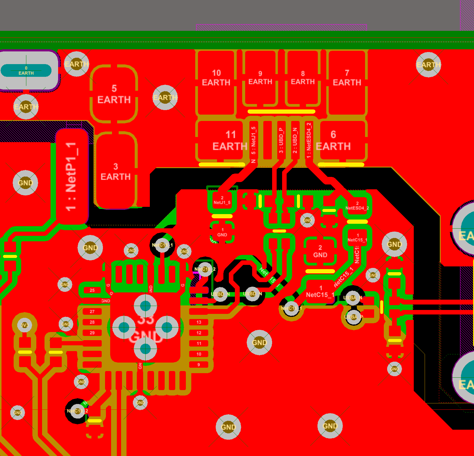
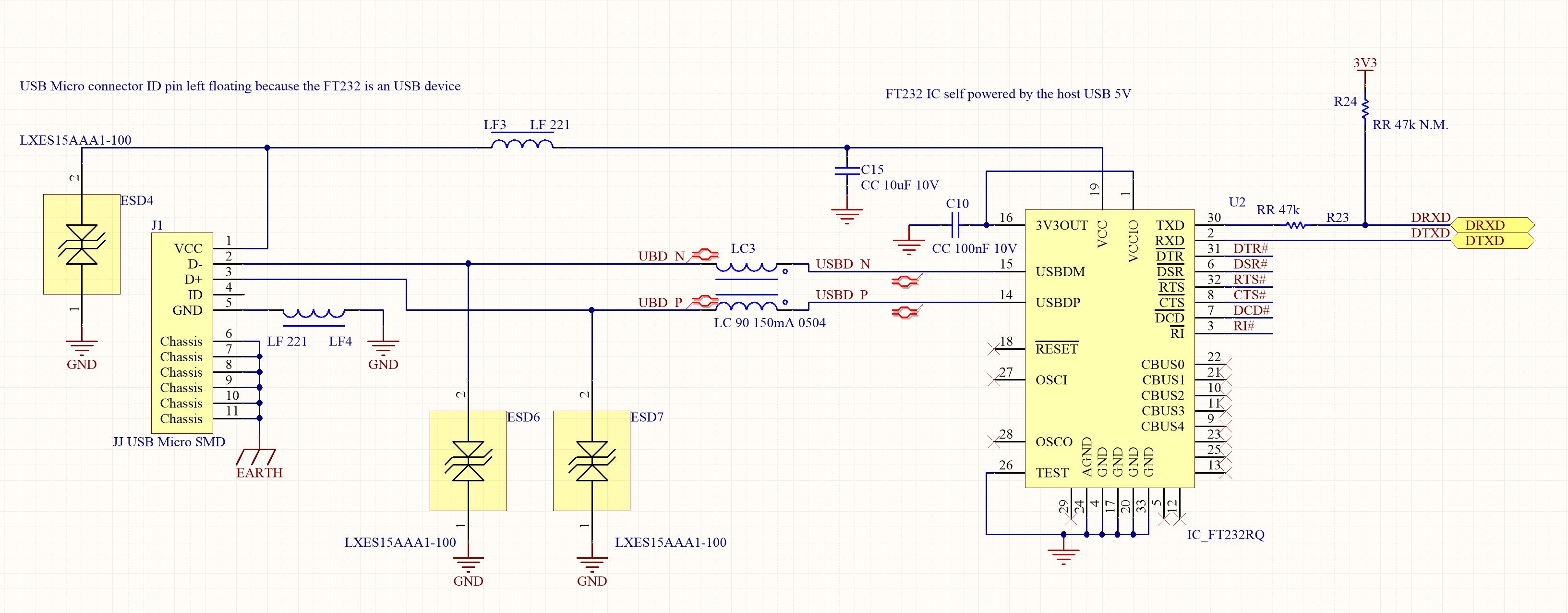 By applying all the cautions described in the article about [USB](https://www.acmesystems.it/usb) for external devices connections, this system guarantees a reliable and stable connection for frequent usage.
 ##RS232
The *EIA RS-232-C standard (August 1969) defines the "Interface Between Data Terminal Equipment and Data Communication Equipment Employing Serial Binary Data Interchange"*, including the signals levels, connector types etc. Even though it has been almost completely replaced by the common USB, it could still be possible to have the need of this type of connection.
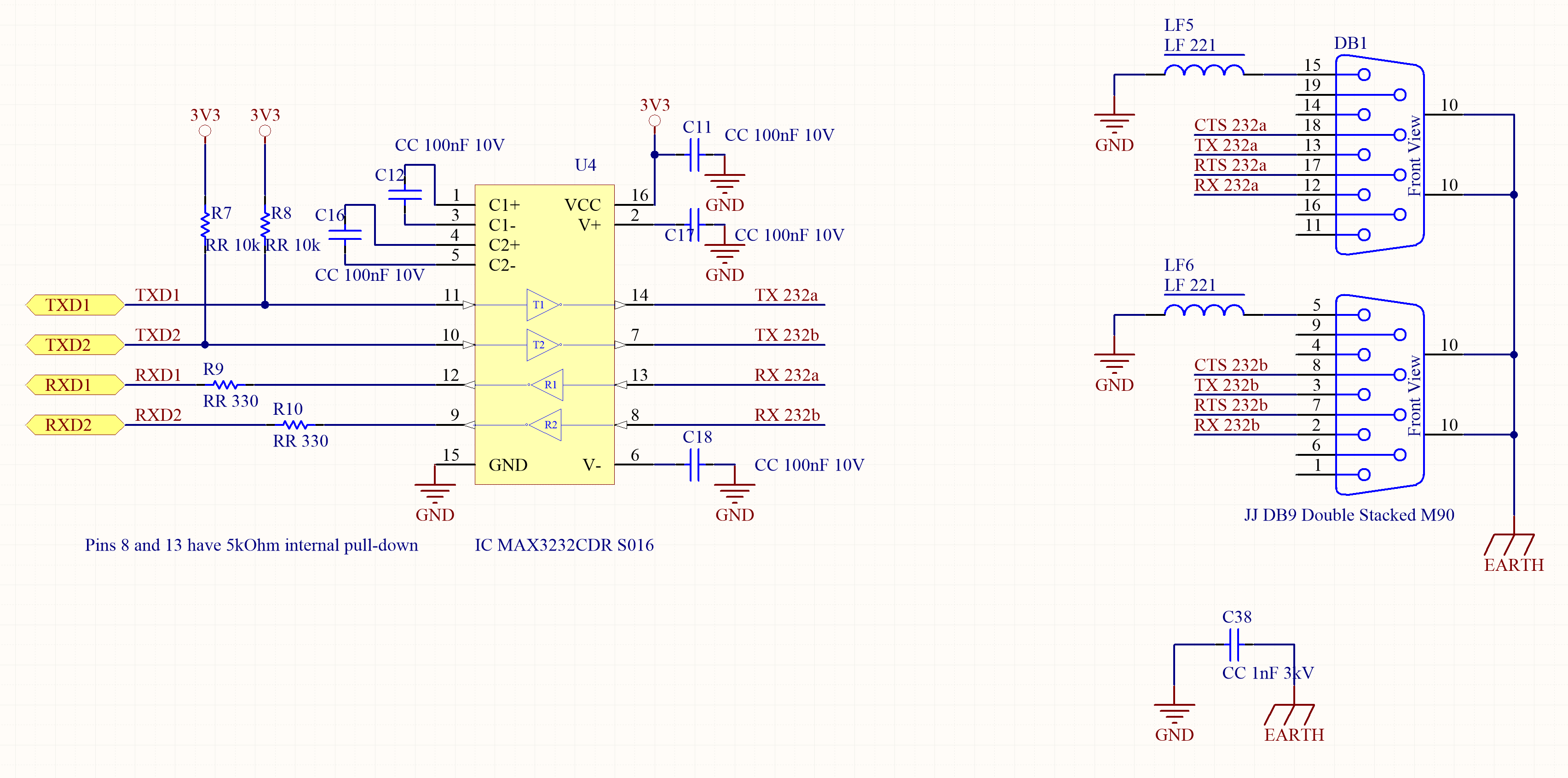
The [MAX3232](http://www.ti.com/lit/ds/symlink/max3232.pdf) Line Driver/Receiver meets or exceeds the requirements of more recent TIA/EIA-232-F and ITU V.28 standards starting from TTL signals and a single 3.3V power supply, including ±15-kV ESD protection.
##RS232
The *EIA RS-232-C standard (August 1969) defines the "Interface Between Data Terminal Equipment and Data Communication Equipment Employing Serial Binary Data Interchange"*, including the signals levels, connector types etc. Even though it has been almost completely replaced by the common USB, it could still be possible to have the need of this type of connection.
The [MAX3232](http://www.ti.com/lit/ds/symlink/max3232.pdf) Line Driver/Receiver meets or exceeds the requirements of more recent TIA/EIA-232-F and ITU V.28 standards starting from TTL signals and a single 3.3V power supply, including ±15-kV ESD protection.
### Q&A
Why do use pullup resistors R7 and R8 ?
The pull-up can be required to ensure the correct idle state of the RS232 OUT TX line even when the MCU is in sleep mode or with the peripheral disabled to save energy. Of course you can avoid them if this is not your case. Usually it’s a good design practice to foresee multiple conditions leaving room on the PCB for some component that can be mounted in production only if really needed.
Why do use use R9 and R10 ?
The series resistor on RX line it’s not so critical. It’s a balance between protection and transparency to the signal. It depends on connections length and on max speed of the communication. If the resistor is too high it can affect the shape of the rising and falling edges of the signal, when combined with a high capacitance of the line in between. This can become crucial at very high bit rate. If the MAX232 is very close to the MCU on the same PCB those can be increased due to the low capacitance of the circuit or avoided at all because no protection is needed.
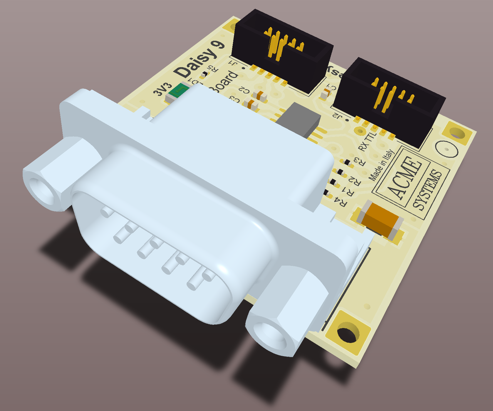
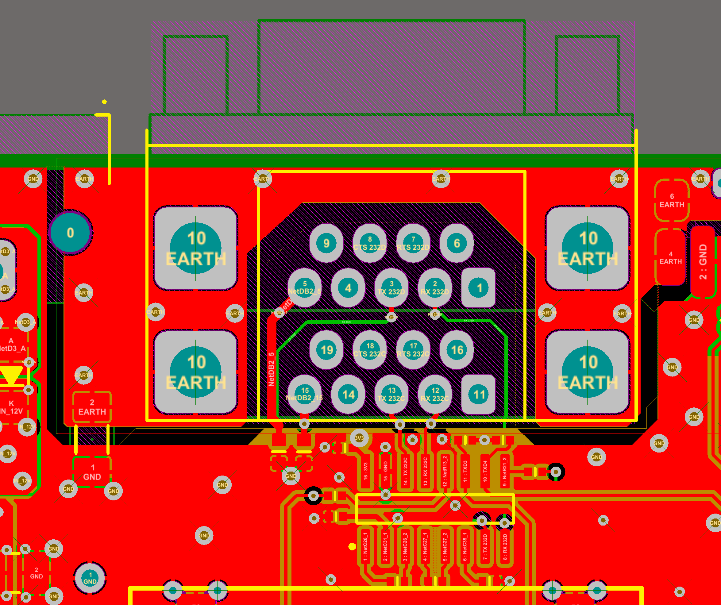
Right now only the DB9 D-sub connector is used for RS232 interfacing.
 If no RTS-CTS handshaking is used, the 2+2 line drivers of the MAX3232 can be used for a double serial connection. In this example four devices can be interfaced, using two double, stacked DB9 D-sub connectors to save space on PCB.
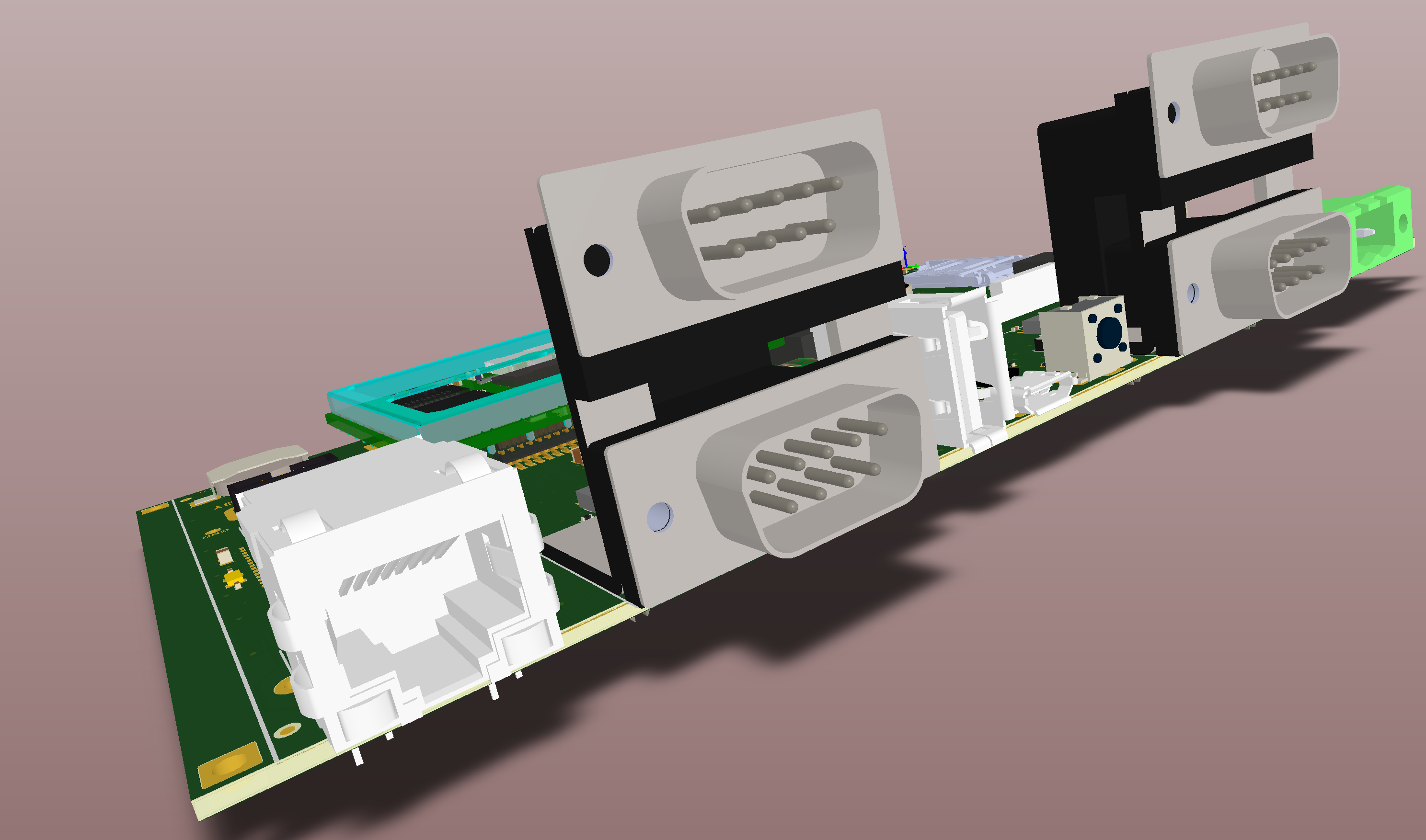 Because of the external connections of the RS232 cable, all the cares already described about ESD must be applied. A 1mm gap between the shield and internal ground guarantees enough tolerance to high voltage. No external ESD protection components are required because they are included in the MAX3232 chip.
 ##Related links
* [Roadrunner USB pinout **(PRELIMINARY)**](./ROADRUNNER-pinout.png)
* [SAMA5D2 Series datasheet](http://ww1.microchip.com/downloads/en/DeviceDoc/60001476A.pdf)
* [FTDI FT232](http://www.ftdichip.com/Support/Documents/DataSheets/ICs/DS_FT232R.pdf)
* [MAX3232](http://www.ti.com/lit/ds/symlink/max3232.pdf)
*
@include='bio_guiott'
##Related links
* [Roadrunner USB pinout **(PRELIMINARY)**](./ROADRUNNER-pinout.png)
* [SAMA5D2 Series datasheet](http://ww1.microchip.com/downloads/en/DeviceDoc/60001476A.pdf)
* [FTDI FT232](http://www.ftdichip.com/Support/Documents/DataSheets/ICs/DS_FT232R.pdf)
* [MAX3232](http://www.ti.com/lit/ds/symlink/max3232.pdf)
*
@include='bio_guiott'