#Getting started with RoadRunner on Berta D2 board
This article explains how to get started with the RoadRunner module and
the Berta D2 evaluation board
##First steps to do to turn-on your Berta D2 board
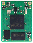
Follow the sequence illustrated on this image to turn-on your board:
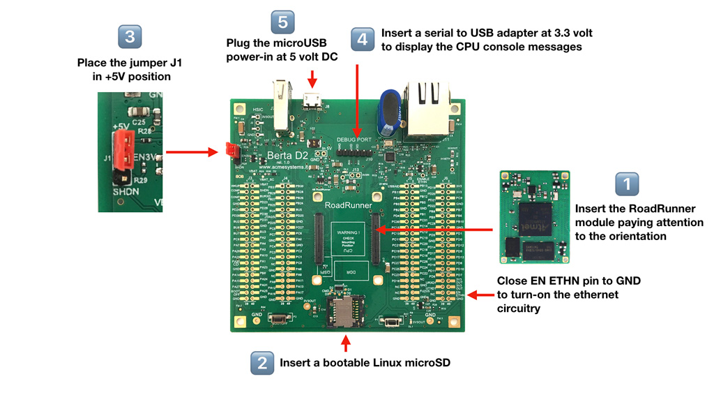
## 1) Insert the Road Runner module
Pay attention with the RoadRunner orientation to avoid electrical damages
## 2) Insert a bootable Linux microSD
You can use one of following microSD:
* A Linux Debian Buster 10 downloaded from: @article='binary_repository'
* An image created from scratch compiling at91bootstrap,Linux Kernel and rootfs: [RoadRunner doc](/doc_roadrunner).
* A ready-to-use microSD bought by: [RoadRunner bootable microSD catalog](/pricelist?category=roadrunner)
@shop='DEBM8G-E-RR'
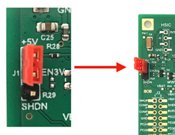
## 3) Place the jumper J1 in +5V position
Probably this is already the default position
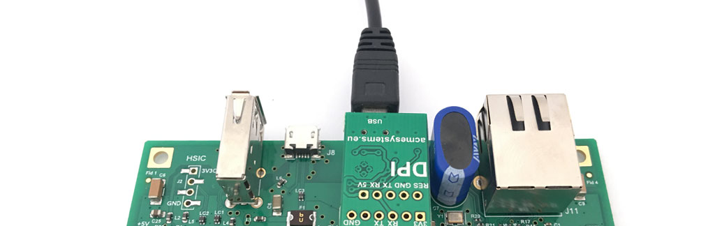
## 4) Insert a serial usb adapter to get access to the debug port from a serial terminal
The serial terminal setings are 115200.N,8,1 with no flow control
From the Acme Systems eShop two USB to serial converters are available. You can use any other one but pay attention about
the electrical signal levels that must be at 3.3 Volt to avoid board damage.
### How to plug the DPI adapter:
@shop='DPI'
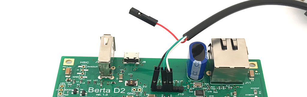
### How to plug the USB-3V-SER adapter:
@shop='USB-3V-SER'
## 5) Enable the MicroSD CD line
If you are using a ROADRUNNER-Q0 that has no quadSPI on-board or a ROADRUNNER-Q16/64/128 without the at91boostrap
stored on it you need to connect the PA30/CD pin on J3 to GND to boot up the board.
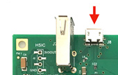
## 6) Plug the microUSB connector to turn-on the board
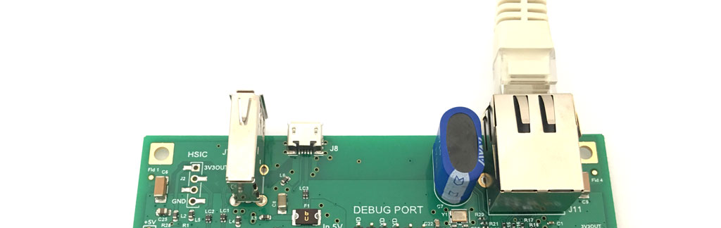
## How to enable the Ethernet port
If you are using a ready-to-use microSD, it is configured to get the IP address from your DHCP server
The LAN circuitry is powered-off by default. The line that controls the PHY power-on is wired to the jumper J15.
You can also use a normal I/O line from the RoadRunner to TP11 to control the power state of the PHY in order to
reduce power consumption when the ETH interface is not needed.
## Bootstrap sequence and login from debug port
By default the RoadRunner starts running __RomBOOT__ a first level bootloader stored in the internal MPU ROM.
This program at power on sends this message to the debug port:
RomBOOT
then it looks for a second level bootloader called [at91bootstrap](/at91bootstrap_3_8). This
program usually is stored by default on the QuadSPI and it starts sending this message to the debug port:
AT91Bootstrap 3.9.1
...
If a bootable microSD is present the following messages will appear:
SD/MMC: Image: Read file zImage to 0x22000000
MMC: ADMA supported
SD: Card Capacity: High or Extended
SD: Specification Version 3.0X
SD/MMC: dt blob: Read file acme-roadrunner.dtb to 0x21000000
Booting zImage ......
Using device tree in place at 0x21000000
Starting linux kernel ..., machid: 0xffffffff
Booting Linux on physical CPU 0x0
Linux version 4.9.40 (ant9000@chomp) (gcc version 4.9.4 (Linaro GCC 4.9-2017.01) ) #1 Tue Oct 2 15:02:27 CEST 2018
The Linux Kernel image boot messages will follow.
The file __zImage__ (compressed Linux Kernel image) and __acme-roadrunner.dtb__ device tree blob file
must be saved on the first FAT16 or FAT32 partition on the microSD.
After the kernel boot there is a second EXT4 partition present on the microSD with the rootfs contents
(Linux system and application programms) that will be loaded and run.
Debian GNU/Linux 10 roadrunner ttyS0
roadrunner login:
Now you can login as:
Login: acme
Password: acmesystems
### Login from remote SSH session
By default the __SSHD__ daemon is installed on the Linux Debian Buster microSD.
Type:
sudo ifconfig eth0
to check the IP assigned by your DHCP to the board:
eth0: flags=4163 mtu 1500
inet 192.168.1.129 netmask 255.255.255.0 broadcast 192.168.1.255
inet6 fe80::243f:8eff:fe10:548e prefixlen 64 scopeid 0x20
ether 26:3f:8e:10:54:8e txqueuelen 1000 (Ethernet)
RX packets 150749 bytes 15841329 (15.1 MiB)
RX errors 0 dropped 7529 overruns 0 frame 0
TX packets 97 bytes 7395 (7.2 KiB)
TX errors 0 dropped 0 overruns 0 carrier 0 collisions 0
device interrupt 27 base 0x8000
Then get access from a remote Linux terminal using this command:
ssh acme@192.168.1.14
The password are always:
Login: acme
Password: acmesystems
### Set the eth0 MAC address
If you have more than one Roadrunner on your LAN the first thing to do is to change the MAC address of your board.
Unfortunately the Roadrunner doesn't have a MAC address chip as like as the [Acqua A5 board](/acqua) so you have to
set it on the microSD or use a [MAC address chip on your application carrier](https://www.acmesystems.it/acqua_at24mac402)
The mac address of eth0 is save on this file:
cat /etc/eth0.macaddress
### Enable the access as root from ssh
By default the access as root from ssh is disabled on Debian Buster 10. To enable it define a password for the root user:
sudo passwd
then edit with nano thie sshf_config file:
sudo nano /etc/ssh/sshd_config
and change this line:
#PermitRootLogin prohibit-password
with:
PermitRootLogin yes
then re-launch sshd
sudo systemctl restart sshd
### Where to go now ?
Basically the RoadRunner is a normal Linux Board so all the tutorials available
on internet about Linux and Debian Linux distributions could be used also on this board.
From the Debian repository all the packages available for the ARMHF architecure should
be working also an RoadRunner without any problem.
To install new packages the command is typically:
sudo apt update
sudo apt install [package-name]
A RoadRunner related list of articles is avalable from this link:
* @article='doc_roadrunner'
## Berta D2 board anatomy
In this section we will continue with the description of any component available on the Berta D2 board
To know the electrical details about the Berta D2 board read the schematic available here
in pdf format:
* [Berta D2 schematic](/www/roadrunner/BertaD2_1_1_schematic.pdf)
### BOOTOFF and RESET push-buttons
The purpose of the BOOTOFF push-button is to prevent the access of the QuadSPI from the CPU at power on.
In this way the RomBOOT bootloader, instead of booting the second level bootloader (at91bootstrap),
will enable the USB device port in order to be able to re-program
the QuadSPI contents from a connected Linux box running SAM-BA utiity.
Hold down the BOOTOFF push-button while pressing the RESET button and release the RESET button first and
the BOOTOFF button 1 second later.
The RomBOOT message will appear on the debug port and the USB device port will go up
to receive command from SAM-BA.
Read the article @article='SAM-BA' to know more on how to re-write the RoadRunner QuadSPI.
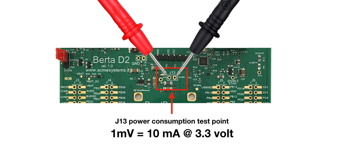
### J13 jumper - Power consumption test point
The J13 pads of the Berta D2 board are used to measure the RoadRunner module power consumption.
Those pads are in parallel with a 0.1 Ohm resistor so that if you put a voltmeter on J13,
every mV measured corresponds to 10 mA of current consumption @ 3.3 Volt.
A summary of the power consumption of the module in several running states is reported here:
[RoadRunner Power Consumption](/power_consumption)
### J1 jumper - Power supply shutdown mode
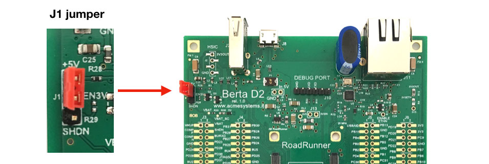
The J1 jumper is to select the desired state of the 5V to 3.3V switching buck regulator.
* Closing +5V - EN3V pins the regulator's ENABLE signal is tied to 5V so
it will remains always on regardless of the state of the RoadRunner shutdown line.
* Closing SHDN - EN3V pins the regulator's ENABLE signal is tied to the
RoadRunner shutdown line so, typing this command shutdown -h now,
the main 3.3V regulator will power off.
In this state to wake up the RoadRunner you need to put the WKUP line (J3.1)
momentarily at GND with a pushbutton or with a wire.
It is also possible to go in shutdown and wake up after an event on a I/O line or with a Real Time Clock timeout.
For example in order to restart the board at a predefined time after the shutdown you can issue the following command immediately
before the "shutdown -h now" or "poweroff" command
echo "+30" > /sys/class/rtc/rtc0/wakealarm
During the shutdown time with the J1 jumper in the bottom position the BertaD2 will consume zero from the external power and the
supercap will maintain the backup zone with Real Time Clock and the logic to wakeup from external events.
### Backup current consumption
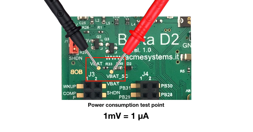
You can measure the current consumption in backup mode on the VBAT_SC and VBAT pads shown below.
Those pads are in parallel with a 1000 Ohm resistor so 1 mV measured corresponds to 1 uA (microampere)
of current consumption from the backup power source (in the Berta D2 there is a supercapacitor as backup power source).
@include='adv_roadrunner'
 ## 1) Insert the Road Runner module
Pay attention with the RoadRunner orientation to avoid electrical damages
## 1) Insert the Road Runner module
Pay attention with the RoadRunner orientation to avoid electrical damages
 ## 2) Insert a bootable Linux microSD
You can use one of following microSD:
* A Linux Debian Buster 10 downloaded from: @article='binary_repository'
* An image created from scratch compiling at91bootstrap,Linux Kernel and rootfs: [RoadRunner doc](/doc_roadrunner).
* A ready-to-use microSD bought by: [RoadRunner bootable microSD catalog](/pricelist?category=roadrunner)
@shop='DEBM8G-E-RR'
## 3) Place the jumper J1 in +5V position
Probably this is already the default position
## 2) Insert a bootable Linux microSD
You can use one of following microSD:
* A Linux Debian Buster 10 downloaded from: @article='binary_repository'
* An image created from scratch compiling at91bootstrap,Linux Kernel and rootfs: [RoadRunner doc](/doc_roadrunner).
* A ready-to-use microSD bought by: [RoadRunner bootable microSD catalog](/pricelist?category=roadrunner)
@shop='DEBM8G-E-RR'
## 3) Place the jumper J1 in +5V position
Probably this is already the default position
 ## 4) Insert a serial usb adapter to get access to the debug port from a serial terminal
The serial terminal setings are 115200.N,8,1 with no flow control
From the Acme Systems eShop two USB to serial converters are available. You can use any other one but pay attention about
the electrical signal levels that must be at 3.3 Volt to avoid board damage.
### How to plug the DPI adapter:
## 4) Insert a serial usb adapter to get access to the debug port from a serial terminal
The serial terminal setings are 115200.N,8,1 with no flow control
From the Acme Systems eShop two USB to serial converters are available. You can use any other one but pay attention about
the electrical signal levels that must be at 3.3 Volt to avoid board damage.
### How to plug the DPI adapter:
 @shop='DPI'
### How to plug the USB-3V-SER adapter:
@shop='DPI'
### How to plug the USB-3V-SER adapter:
 @shop='USB-3V-SER'
## 5) Enable the MicroSD CD line
If you are using a ROADRUNNER-Q0 that has no quadSPI on-board or a ROADRUNNER-Q16/64/128 without the at91boostrap
stored on it you need to connect the PA30/CD pin on J3 to GND to boot up the board.
## 6) Plug the microUSB connector to turn-on the board
@shop='USB-3V-SER'
## 5) Enable the MicroSD CD line
If you are using a ROADRUNNER-Q0 that has no quadSPI on-board or a ROADRUNNER-Q16/64/128 without the at91boostrap
stored on it you need to connect the PA30/CD pin on J3 to GND to boot up the board.
## 6) Plug the microUSB connector to turn-on the board
 ## How to enable the Ethernet port
If you are using a ready-to-use microSD, it is configured to get the IP address from your DHCP server
## How to enable the Ethernet port
If you are using a ready-to-use microSD, it is configured to get the IP address from your DHCP server
 The LAN circuitry is powered-off by default. The line that controls the PHY power-on is wired to the jumper J15.
You can also use a normal I/O line from the RoadRunner to TP11 to control the power state of the PHY in order to
reduce power consumption when the ETH interface is not needed.
## Bootstrap sequence and login from debug port
By default the RoadRunner starts running __RomBOOT__ a first level bootloader stored in the internal MPU ROM.
This program at power on sends this message to the debug port:
RomBOOT
then it looks for a second level bootloader called [at91bootstrap](/at91bootstrap_3_8). This
program usually is stored by default on the QuadSPI and it starts sending this message to the debug port:
AT91Bootstrap 3.9.1
...
If a bootable microSD is present the following messages will appear:
SD/MMC: Image: Read file zImage to 0x22000000
MMC: ADMA supported
SD: Card Capacity: High or Extended
SD: Specification Version 3.0X
SD/MMC: dt blob: Read file acme-roadrunner.dtb to 0x21000000
Booting zImage ......
Using device tree in place at 0x21000000
Starting linux kernel ..., machid: 0xffffffff
Booting Linux on physical CPU 0x0
Linux version 4.9.40 (ant9000@chomp) (gcc version 4.9.4 (Linaro GCC 4.9-2017.01) ) #1 Tue Oct 2 15:02:27 CEST 2018
The Linux Kernel image boot messages will follow.
The file __zImage__ (compressed Linux Kernel image) and __acme-roadrunner.dtb__ device tree blob file
must be saved on the first FAT16 or FAT32 partition on the microSD.
After the kernel boot there is a second EXT4 partition present on the microSD with the rootfs contents
(Linux system and application programms) that will be loaded and run.
Debian GNU/Linux 10 roadrunner ttyS0
roadrunner login:
Now you can login as:
Login: acme
Password: acmesystems
### Login from remote SSH session
By default the __SSHD__ daemon is installed on the Linux Debian Buster microSD.
Type:
sudo ifconfig eth0
to check the IP assigned by your DHCP to the board:
eth0: flags=4163
The LAN circuitry is powered-off by default. The line that controls the PHY power-on is wired to the jumper J15.
You can also use a normal I/O line from the RoadRunner to TP11 to control the power state of the PHY in order to
reduce power consumption when the ETH interface is not needed.
## Bootstrap sequence and login from debug port
By default the RoadRunner starts running __RomBOOT__ a first level bootloader stored in the internal MPU ROM.
This program at power on sends this message to the debug port:
RomBOOT
then it looks for a second level bootloader called [at91bootstrap](/at91bootstrap_3_8). This
program usually is stored by default on the QuadSPI and it starts sending this message to the debug port:
AT91Bootstrap 3.9.1
...
If a bootable microSD is present the following messages will appear:
SD/MMC: Image: Read file zImage to 0x22000000
MMC: ADMA supported
SD: Card Capacity: High or Extended
SD: Specification Version 3.0X
SD/MMC: dt blob: Read file acme-roadrunner.dtb to 0x21000000
Booting zImage ......
Using device tree in place at 0x21000000
Starting linux kernel ..., machid: 0xffffffff
Booting Linux on physical CPU 0x0
Linux version 4.9.40 (ant9000@chomp) (gcc version 4.9.4 (Linaro GCC 4.9-2017.01) ) #1 Tue Oct 2 15:02:27 CEST 2018
The Linux Kernel image boot messages will follow.
The file __zImage__ (compressed Linux Kernel image) and __acme-roadrunner.dtb__ device tree blob file
must be saved on the first FAT16 or FAT32 partition on the microSD.
After the kernel boot there is a second EXT4 partition present on the microSD with the rootfs contents
(Linux system and application programms) that will be loaded and run.
Debian GNU/Linux 10 roadrunner ttyS0
roadrunner login:
Now you can login as:
Login: acme
Password: acmesystems
### Login from remote SSH session
By default the __SSHD__ daemon is installed on the Linux Debian Buster microSD.
Type:
sudo ifconfig eth0
to check the IP assigned by your DHCP to the board:
eth0: flags=4163 Read the article @article='SAM-BA' to know more on how to re-write the RoadRunner QuadSPI.
### J13 jumper - Power consumption test point
The J13 pads of the Berta D2 board are used to measure the RoadRunner module power consumption.
Those pads are in parallel with a 0.1 Ohm resistor so that if you put a voltmeter on J13,
every mV measured corresponds to 10 mA of current consumption @ 3.3 Volt.
A summary of the power consumption of the module in several running states is reported here:
[RoadRunner Power Consumption](/power_consumption)
Read the article @article='SAM-BA' to know more on how to re-write the RoadRunner QuadSPI.
### J13 jumper - Power consumption test point
The J13 pads of the Berta D2 board are used to measure the RoadRunner module power consumption.
Those pads are in parallel with a 0.1 Ohm resistor so that if you put a voltmeter on J13,
every mV measured corresponds to 10 mA of current consumption @ 3.3 Volt.
A summary of the power consumption of the module in several running states is reported here:
[RoadRunner Power Consumption](/power_consumption)
 ### J1 jumper - Power supply shutdown mode
 The J1 jumper is to select the desired state of the 5V to 3.3V switching buck regulator.
* Closing +5V - EN3V pins the regulator's ENABLE signal is tied to 5V so
it will remains always on regardless of the state of the RoadRunner shutdown line.
* Closing SHDN - EN3V pins the regulator's ENABLE signal is tied to the
RoadRunner shutdown line so, typing this command shutdown -h now,
the main 3.3V regulator will power off.
In this state to wake up the RoadRunner you need to put the WKUP line (J3.1)
momentarily at GND with a pushbutton or with a wire.
It is also possible to go in shutdown and wake up after an event on a I/O line or with a Real Time Clock timeout.
For example in order to restart the board at a predefined time after the shutdown you can issue the following command immediately
before the "shutdown -h now" or "poweroff" command
echo "+30" > /sys/class/rtc/rtc0/wakealarm
During the shutdown time with the J1 jumper in the bottom position the BertaD2 will consume zero from the external power and the
supercap will maintain the backup zone with Real Time Clock and the logic to wakeup from external events.
### Backup current consumption
You can measure the current consumption in backup mode on the VBAT_SC and VBAT pads shown below.
The J1 jumper is to select the desired state of the 5V to 3.3V switching buck regulator.
* Closing +5V - EN3V pins the regulator's ENABLE signal is tied to 5V so
it will remains always on regardless of the state of the RoadRunner shutdown line.
* Closing SHDN - EN3V pins the regulator's ENABLE signal is tied to the
RoadRunner shutdown line so, typing this command shutdown -h now,
the main 3.3V regulator will power off.
In this state to wake up the RoadRunner you need to put the WKUP line (J3.1)
momentarily at GND with a pushbutton or with a wire.
It is also possible to go in shutdown and wake up after an event on a I/O line or with a Real Time Clock timeout.
For example in order to restart the board at a predefined time after the shutdown you can issue the following command immediately
before the "shutdown -h now" or "poweroff" command
echo "+30" > /sys/class/rtc/rtc0/wakealarm
During the shutdown time with the J1 jumper in the bottom position the BertaD2 will consume zero from the external power and the
supercap will maintain the backup zone with Real Time Clock and the logic to wakeup from external events.
### Backup current consumption
You can measure the current consumption in backup mode on the VBAT_SC and VBAT pads shown below.
 Those pads are in parallel with a 1000 Ohm resistor so 1 mV measured corresponds to 1 uA (microampere)
of current consumption from the backup power source (in the Berta D2 there is a supercapacitor as backup power source).
@include='adv_roadrunner'
Those pads are in parallel with a 1000 Ohm resistor so 1 mV measured corresponds to 1 uA (microampere)
of current consumption from the backup power source (in the Berta D2 there is a supercapacitor as backup power source).
@include='adv_roadrunner'