# How to use the SPI ports
This article illustrates how to use the SPI on Acme Systems Linux boards based on Microchip
SAMG25, SAMA5D3x
## Pinout of SPI ports
The SPI bus lines are located on the following pins:
| Signal | Dir | Description | Roadrunner | Acqua | Aria | Arietta |
|------------|-----|-----------------------------|------------|--------------|------------|--------------|
| SPI0 MOSI | O | Master Output Slave Input | | J2.7 (PD11) | S11 (PA12) | |
| SPI0 MISO | I | Master Input Slave Output | | J2.8 (PD10) | S12 (PA11) | |
| SPI0 SCLK | O | Clock | | J2.6 (PD12) | S10 (PA13) | |
| SPI0 CS0 | O | Chip Select 0 | | J2.5 (PD13) | S9 (PA14) | |
| SPI0 CS1 | O | Chip Select 1 | | J2.10 (PD14) | S16 (PA7) | |
| SPI0 CS2 | O | Chip Select 2 | | J2.9 (PD15) | S22 (PA1) | |
| SPI0 CS3 | O | Chip Select 3 | | J2.12 (PD16) | | |
| SPI1 MOSI | O | Master Output Slave Input | | J3.22 (PC23) | | J4.8 (PA22) |
| SPI1 MISO | I | Master Input Slave Output | | J3.24 (PC22) | | J4.10 (PA21) |
| SPI1 SCLK | O | Clock | | J3.25 (PC24) | | J4.7 (PA23) |
| SPI1 CS0 | O | Chip Select 0 | | J3.23 (PC25) | | J4.25 (PA8) |
| SPI1 CS1 | O | Chip Select 1 | | J3.26 (PC26) | | J4.23 (PA0) |
| SPI1 CS2 | O | Chip Select 2 | | J3.28 (PC27) | | J4.12 (PA31) |
| SPI1 CS3 | O | Chip Select 3 | | J3.29 (PC28) | | J4.14 (PA30) |
Not all the signales are available by default and not all SPI lines are listed on this table or muxed in this way.
Refer to the MCU datasheets to find other lines.
## Enable the Linux Kernel SPI modules
Follow this tutorial: @h1='compile_linux_kernel' to know how to cross compile the Linux Kernel
and how to configure the drivers to enable inside it.
Enable the SPIDEV user interface and the Microchip SPI device driver
as shown below:
Device Drivers --->
[*] SPI support --->
<*> Atmel SPI Controller
<*> User mode SPI device driver support
## Configure the device tree
Edit the device tree source of your board adding these lines:
#### Acqua
spi0: spi@f0004000 {
status = "okay";
cs-gpios = <&pioD 13 0>, <&pioD 14 0>, <&pioD 15>, <&pioD 16>;
device@0 {
compatible = "spidev";
spi-max-frequency = <50000000>; // 50 MHz
reg = <0>;
};
device@1 {
compatible = "spidev";
spi-max-frequency = <5000000>; // 5 MHz
reg = <1>;
};
device@2 {
compatible = "spidev";
spi-max-frequency = <5000000>; // 5 MHz
reg = <2>;
};
device@3 {
compatible = "spidev";
spi-max-frequency = <5000000>; // 5 MHz
reg = <3>;
};
};
spi1: spi@f8008000 {
status = "disabled";
cs-gpios = <&pioC 25 0>, <&pioC 26 0>, <&pioC 27 0>, <&pioC 28 0>;
};
#### Aria
spi0: spi@f0000000 {
status = "okay";
interrupts = <13 4 5>;
cs-gpios = <&pioA 14 0>, <&pioA 7 0>, <&pioA 1 0>, <&pioB 3 0>;
device@0 {
compatible = "spidev";
spi-max-frequency = <5000000>;
reg = <0>;
};
device@1 {
compatible = "spidev";
spi-max-frequency = <5000000>;
reg = <1>;
};
device@2 {
compatible = "spidev";
spi-max-frequency = <5000000>;
reg = <2>;
};
device@3 {
compatible = "spidev";
spi-max-frequency = <5000000>;
reg = <3>;
};
};
Credits: Many thanks to Marcelo Roberto Jimenez for his contribute on this section
#### Arietta
spi1: spi@f0004000 {
status = "okay";
cs-gpios = <&pioA 8 0>, <&pioA 0 0>, <&pioA 31 0>, <&pioA 30 0>;
device@0 {
compatible = "spidev";
spi-max-frequency = <50000000>; // 50 MHz
reg = <0>;
};
device@1 {
compatible = "spidev";
spi-max-frequency = <5000000>; // 5 MHz
reg = <1>;
};
device@2 {
compatible = "spidev";
spi-max-frequency = <5000000>; // 5 MHz
reg = <2>;
};
device@3 {
compatible = "spidev";
spi-max-frequency = <5000000>; // 5 MHz
reg = <3>;
};
};
## Check the system log
When you reboot the board you should see a message like this:
[ 0.820312] atmel_spi f0000000.spi: version: 0x212
[ 0.820312] atmel_spi f0000000.spi: Using dma0chan2 (tx) and dma0chan3 (rx) for DMA transfers
[ 0.828125] atmel_spi f0000000.spi: Atmel SPI Controller at 0xf0000000 (irq 29)
by typing the command:
dmesg
## Check that exist the device inside the /dev directory:
ls /dev/spi*
/dev/spidev32766.0
In this case the name /dev/spidev32766.0 is the filename to use to manage the communication
with the SPI device
## Use the SPI from user space
This is an example on how to use the SPI interface from user space using the device file /dev/spidev32766.0 created
by the spidev driver.
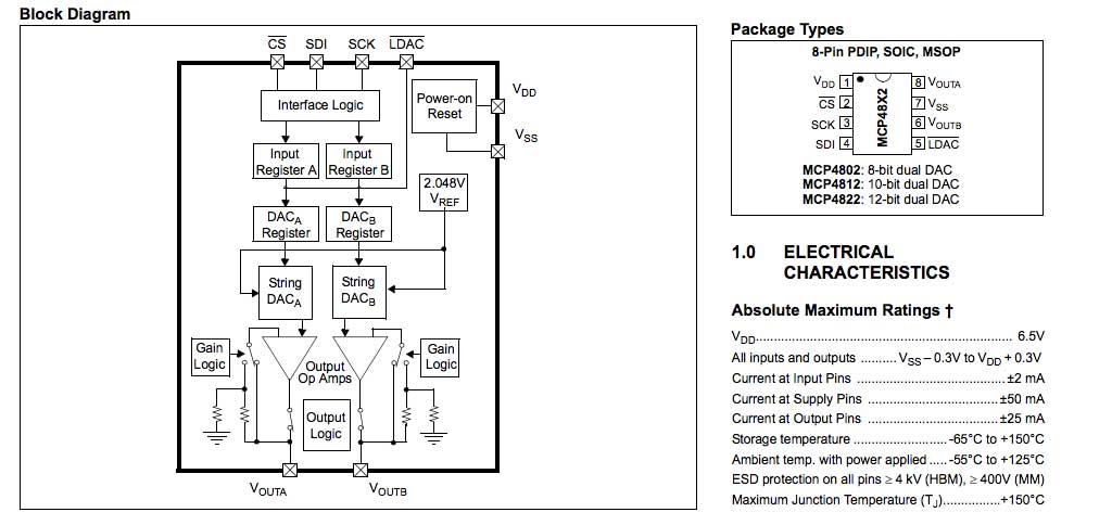
We will use a Microchip SPI DAC model MCP4822
 wired to the Aria G25 SOM in this way:
| MCP4822 | ARIA | SAM9G20 |
|---------|--------|--------------|
| 1 VDD | 3V3 | |
| 2 CS | S9 | PA14 - NPCS0 |
| 3 SCK | S10 | PA13 - SPCK |
| 4 SDI | S11 | PA12 - MOSI |
| 5 LDAC | GND | |
| 6 VOUTB | OUT B | |
| 7 VSS | GND | |
| 8 VOUTA | OUT A | |
with this C program we can set the VOUT A and VOUT B voltage in a range od 0 to 2 volt.
* [mcp4822.c](./mcp4822.c)
Save this program on Aria and compile it by typing
gcc mcp4822.c -std=c99 -o mcp4822
If the C compiler gcc is not found install it by typing:
apt-get install gcc
To set for example the VOUT A at 1.1 volt and the VOUT B at 1.5 volt type:
./mcp4822 1.1 1.7
wired to the Aria G25 SOM in this way:
| MCP4822 | ARIA | SAM9G20 |
|---------|--------|--------------|
| 1 VDD | 3V3 | |
| 2 CS | S9 | PA14 - NPCS0 |
| 3 SCK | S10 | PA13 - SPCK |
| 4 SDI | S11 | PA12 - MOSI |
| 5 LDAC | GND | |
| 6 VOUTB | OUT B | |
| 7 VSS | GND | |
| 8 VOUTA | OUT A | |
with this C program we can set the VOUT A and VOUT B voltage in a range od 0 to 2 volt.
* [mcp4822.c](./mcp4822.c)
Save this program on Aria and compile it by typing
gcc mcp4822.c -std=c99 -o mcp4822
If the C compiler gcc is not found install it by typing:
apt-get install gcc
To set for example the VOUT A at 1.1 volt and the VOUT B at 1.5 volt type:
./mcp4822 1.1 1.7
 ## Datasheets
* [AT91SAM9G20 datasheet](http://www.atmel.com/devices/SAM9G20.aspx?tab=overview) used on FOX Board G20 and Netus G20
* [AT91SAM9G25 datasheet](http://www.atmel.com/devices/SAM9G25.aspx) used on Aria G25 and Terra Board
* [SAMA5D3 ARM Cortex-A5 Microprocessors datasheet](http://www.atmel.com/products/microcontrollers/arm/sama5d3.aspx) used on Acqua A5
* [Microchip MCP4822 device overview](https://www.microchip.com/wwwproducts/en/MCP4822)
* [Microchip MCP4822 datasheet](http://ww1.microchip.com/downloads/en/DeviceDoc/20002249B.pdf)
## Related links
* [Kernel documentation of spidev](http://www.kernel.org/doc/Documentation/spi/spidev)
* [Kernel documentation of SPI](http://www.kernel.org/doc/Documentation/spi/spi-summary)
* @article='spi_linux_26'
@include='bio_tanzilli'
## Datasheets
* [AT91SAM9G20 datasheet](http://www.atmel.com/devices/SAM9G20.aspx?tab=overview) used on FOX Board G20 and Netus G20
* [AT91SAM9G25 datasheet](http://www.atmel.com/devices/SAM9G25.aspx) used on Aria G25 and Terra Board
* [SAMA5D3 ARM Cortex-A5 Microprocessors datasheet](http://www.atmel.com/products/microcontrollers/arm/sama5d3.aspx) used on Acqua A5
* [Microchip MCP4822 device overview](https://www.microchip.com/wwwproducts/en/MCP4822)
* [Microchip MCP4822 datasheet](http://ww1.microchip.com/downloads/en/DeviceDoc/20002249B.pdf)
## Related links
* [Kernel documentation of spidev](http://www.kernel.org/doc/Documentation/spi/spidev)
* [Kernel documentation of SPI](http://www.kernel.org/doc/Documentation/spi/spi-summary)
* @article='spi_linux_26'
@include='bio_tanzilli'