#Working with SPI bus under Linux Kernel 2.6.x
##Aria G25
To enable and configure the SPI bus on Aria G25 (or Terra) using the Kernel 2.6.39
we have to edit a source file inside the Kernel tree:
* [board-sam9x5ek.c](https://github.com/tanzilli/ariag25-linux-2.6.39/blob/ariag25/arch/arm/mach-at91/board-sam9x5ek.c#L151)
The CS0 pin is defined as first element in this struct:
static struct spi_board_info ariag25_spi_devices[] = {
    {
        .modalias    = "spidev",
        .chip_select    = 0,
        .max_speed_hz    = 10 * 1000 * 1000,
        .bus_num    = 0,
        .mode = SPI_MODE_3,
    },
};
To enable the CS1 signal simply add a second element to the struct in that way:
static struct spi_board_info ariag25_spi_devices[] = {
    {
        .modalias    = "spidev",
        .chip_select    = 0,
        .max_speed_hz    = 10 * 1000 * 1000,
        .bus_num    = 0,
        .mode = SPI_MODE_3,
    },

	{
		.modalias    = "spidev",
		.chip_select    = 1,
		.max_speed_hz    = 10 * 1000 * 1000,
		.bus_num    = 1,
		.mode = SPI_MODE_3,
	},
};
To enable the CS2 signal add another element to the struct as shown
below but disable the **TTY0** peripheral (**/dev/tty1** device). Note that
on the [Terra-M board](/terra) this line is used by the GPRS modem.
	{
		.modalias    = "spidev",
		.chip_select    = 2,
		.max_speed_hz    = 10 * 1000 * 1000,
		.bus_num    = 1,
		.mode = SPI_MODE_3,
	},
};
To disable the **TTY0** peripheral (**/dev/tty1**) change the line:
	/* USART0 on /dev/ttyS1. (RX,TX,RTS,CTS) */
	at91_register_uart(AT91SAM9X5_ID_USART0,1,ATMEL_UART_RTS|ATMEL_UART_CTS);
in:
	/* USART0 on /dev/ttyS1. (RX,TX,RTS,CTS) */
	/* at91_register_uart(AT91SAM9X5_ID_USART0,1,ATMEL_UART_RTS|ATMEL_UART_CTS); */
To generate a new kernel image and use it on the Aria G25 or Terra board read this article:
* @article='ariag25_compile_linux_2_6_39'.
##FOX Board G20
To enable and configure the SPI bus on FOX Board G20 using the Kernel 2.6.38 we have to edit a source
file inside the Kernel tree:
* [board-foxg20.c](https://github.com/tanzilli/foxg20-linux-2.6.38/blob/acme-2.6.38/arch/arm/mach-at91/board-foxg20.c#L128).
After this section:
static struct spi_board_info foxg20_spi_devices[] = {
#if !defined(CONFIG_MMC_AT91)
	{
		.modalias	= "mtd_dataflash",
		.chip_select	= 1,
		.max_speed_hz	= 15 * 1000 * 1000,
		.bus_num	= 0,
	},
#endif
add these lines:
static struct spi_board_info foxg20_spi_devices[] = {
	// Add CS0

	{
		.modalias    = "spidev",
		.chip_select    = 0,
		.max_speed_hz    = 10 * 1000 * 1000,
		.bus_num    = 1,
		.mode = SPI_MODE_3,
	},

	// Add CS1

	{
		.modalias    = "spidev",
		.chip_select    = 1,
		.max_speed_hz    = 10 * 1000 * 1000,
		.bus_num    = 1,
		.mode = SPI_MODE_3,
	},

	// Add CS2

	{
		.modalias    = "spidev",
		.chip_select    = 2,
		.max_speed_hz    = 10 * 1000 * 1000,
		.bus_num    = 1,
		.mode = SPI_MODE_3,
	},

	// Add CS3
	{
		.modalias    = "spidev",
		.chip_select    = 3,
		.max_speed_hz    = 10 * 1000 * 1000,
		.bus_num    = 1,
		.mode = SPI_MODE_3,
	},
};
To generate a new kernel image and use it on the FOX Board G20 read this article:
* @article='compile_linux_2_6_38'.
##SPI signals
As stated before the SPI mode is an important parameter that should be
trimmed according to your slave device and in accompliance with the modes
available [here](http://lxr.linux.no/linux+v2.6.38/include/linux/spi/spi.h#L69).
Now follow some graphs of the spidev behaviours captured with an oscilloscope.
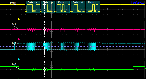
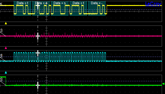
In the following images the cyan trace is the SCLK signal, the yellow trace is MOSI signal and at the end the green trace is n-th CS.
## Spidev on CS0
The trace below was captured using the following Kernel definition:
    {
        .modalias    = "spidev",
        .chip_select    = 0,
        .max_speed_hz    = 1000000,
        .bus_num    = 1,
        .mode = SPI_MODE_3,
    },
and the following command:
echo spi0 > /dev/spidev1.0
Note that the training char in the captured image is a carrier return introduced by echo.
 ## Spidev on CS1
The trace below was captured using the following Kernel definition:
## Spidev on CS1
The trace below was captured using the following Kernel definition:
    {
        .modalias    = "spidev",
        .chip_select    = 1,
        .max_speed_hz    = 1000000,
        .bus_num    = 1,
        .mode = SPI_MODE_1,
    },
and the following command:
echo test > /dev/spidev1.1* command as spidev writer.
Note that using a mode1 the behaviour of clock signal is different.
 ## Spidev on CS2
The trace below was captured using the following Kernel definition:
## Spidev on CS2
The trace below was captured using the following Kernel definition:
    {
        .modalias    = "spidev",
        .chip_select    = 2,
        .max_speed_hz    = 1000000,
        .bus_num    = 1,
        .mode = SPI_MODE_3 | SPI_LSB_FIRST,
    },
and the following command:
echo -n spi2 > /dev/spidev1.2
Note that in this final capture the mode is the binary OR of more than one flag defined inside [spi.h kernel header](http://lxr.linux.no/linux+v2.6.38/include/linux/spi/spi.h#L69).
The captured traces show also that the byte-ordering is inverted due to SPI_LSB_FIRST flag and also that only 4 char are sent on the bus due to the -n option of echo command that supprime the carrier return.