# Termoigrometro ST02
L'ST02 è un termoigrometro RS485 progettato per Valter Violanti adattando la scheda Acme Systems Harvest
per simulare il funzionamento della vecchia verstione ST01 basata su PICMicro
## Appunti per Riccardo
Modifica indirizzo nel sorgente:
* Accendere la Raspberry Pi 400
* Cliccare sull'icona del File Manager in alto a sinistra
* Spostarsi nella directory /home/pi/lora3a-st01
* Click tasto destro su main.c e selezionare geany
* Cambiare l'indirizzo a riga 20
* Salvare il file
Programmazione scheda
* Aprire una sessione terminale (sempre in alto a sinistra)
Dare il seguenti comandi:
cd lora3a-st02
Quindi inserire il programmatore e dare il seguente comando:
sudo make flash
## Repository GitHub
*
## Installazione RIOT e SDK
* @article='st02-riot'
## Pinout modulo Harvest
ICSP J6 SERIAL
------- -------
| 1 2 | | RX |
| 3 4 | | TX |
| 5 6 | | GND |
------- -------
Acme bus pinout on SAML21 site
| Pin # | Signal | | |
|-------|-----------|-----------|-----|
| 1 | VCC @ 3V3 | | VCC |
| 2 | PA05 | Ser0Pad1 | RXD |
| 3 | PA04 | Ser0Pad0 | TXD |
| 4 | PA06 | Ser0Pad2 | RTS |
| 5 | PA07 | Ser0Pad3 | CTS |
| 6 | GND | | GND |
Acme bus pinout on RS485 carrier site
| Pin # | Signal | | |
|-------|-----------|-----------|-----|
| 1 | GND | | GND |
| 2 | PA07 | Ser0Pad3 | CTS |
| 3 | PA06 | Ser0Pad2 | RTS |
| 4 | PA04 | Ser0Pad0 | TXD |
| 5 | PA05 | Ser0Pad1 | RXD |
| 6 | VCC @ 3V3 | | VCC |
## Connession tra Atmel ICE e scheda harvest ICSP (Connettor J6)
| Atmel ICE| Harvest |
|----------|---------|
| 1 | 5 |
| 2 | |
| 3 | |
| 4 | |
| 5 | |
| 6 | 6 |
| 7 | 4 |
| 8 | |
| 9 | 3 |
| 10 | 2 |
## Il protocollo SNAP
Descrizione del protocollo:
* [Protocollo](https://pi3g.com/2019/04/23/introduction-to-the-snap-protocol/)
Struttura del pacchetto:
 * SYNC: unique byte with the following structure: 01010100 (0x54), indicates the start of the packet
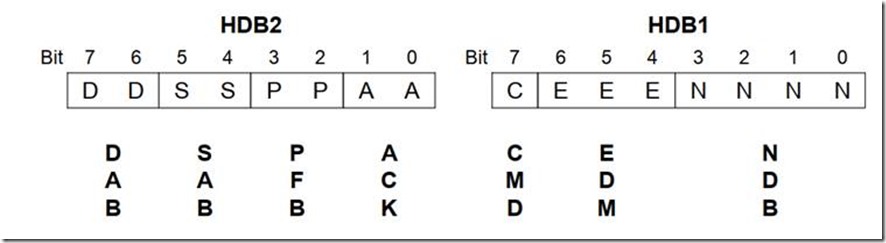
* HDB2, HDB1: The header definition bytes HDB2 and HDB1 define how long the packet will be, and which features will be used.
* DAB1: Destination Address Byte (0x12 per il PIC campione)
* SAB1: Source Address Byte (0x00 per il PC)
* DB1: Data Byte 1 – the payload for your application
* CRC2: high byte of CRC-16
* CRC1: low byte of CRC-16
Address 0 is reserved as a broadcast address and should not be used for anything else. (DAB / SAB)
Nel caso di Valter abbiamo per HDB2
* DD=01 (Un byte di indirizzo destinazione)
* SS=01 (Un byte di indirizzo sorgente)
* PP=00 Non usato
* AA
* 00 = No Ack request (Tx)
* 01 = Ack request (Tx)
* 10 = Ack response (Rx)
* 11 = NAK response (Rx)
e per HDB1
* CMD=0
* EDM=error detection method 100 = 16 bit CRC.
* NDB=Numero di byte nel campo DB1
* SYNC: unique byte with the following structure: 01010100 (0x54), indicates the start of the packet
* HDB2, HDB1: The header definition bytes HDB2 and HDB1 define how long the packet will be, and which features will be used.
* DAB1: Destination Address Byte (0x12 per il PIC campione)
* SAB1: Source Address Byte (0x00 per il PC)
* DB1: Data Byte 1 – the payload for your application
* CRC2: high byte of CRC-16
* CRC1: low byte of CRC-16
Address 0 is reserved as a broadcast address and should not be used for anything else. (DAB / SAB)
Nel caso di Valter abbiamo per HDB2
* DD=01 (Un byte di indirizzo destinazione)
* SS=01 (Un byte di indirizzo sorgente)
* PP=00 Non usato
* AA
* 00 = No Ack request (Tx)
* 01 = Ack request (Tx)
* 10 = Ack response (Rx)
* 11 = NAK response (Rx)
e per HDB1
* CMD=0
* EDM=error detection method 100 = 16 bit CRC.
* NDB=Numero di byte nel campo DB1
 Trasmissione di una richiesta dall'applicativo di Valter
Da Master a Nodo slave
| 54 | 51 | 41 | 12 | 00 | 02 | 34 | C8 |
| SYNC | HDB2 | HDB1 | PC ADDR | PIC ADDR | PAYLOAD | CRC2 | CRC1 |
HDB2=0x51
1 byte di indirizzo destinazione
1 byte di indirizzo sorgente
Ack richiesto
HDB=0x41
1 byte dati
16 bit CRC
Calcolo on-line del CRC-16
*
* [Arduino SNAP Library](https://github.com/PHaroZ/arduino-snap)
* [ArduinoRS485 library]()
platformio.ini
lib_deps =
arduino-libraries/ArduinoRS485 @ ^1.0.2
Sorgente PIC
* [T628A16.ASM](./T628A16.ASM)
## Server M.A.M.B.A.
Elenco dei processi lanciato con cron
sudo crontab l-
Programma in c usato per fare l'interrogazione del nodo
/usr/sbin/getnode
## Calcolo del CRC16
/ Online C compiler to run C program online
#include
void Crc16(unsigned short *crc, char c) {
int i,j;
for (i=0; i!=8; c>>=1, i++) {
j = (c^(*crc)) & 1;
(*crc)>>=1;
if (j) {
(*crc)^=0xa001;
}
}
}
unsigned char data[]={0x51,0x41,0x12,0x00,0x02};
int main() {
unsigned short crc=0x0;
for (int i=0;i<5;i++) {
Crc16(&crc,data[i]);
printf("0x%02x\n",data[i]);
}
// Write C code here
printf("0x%04x\n",crc);
return 0;
}
## Prove fatte con ESP-32
ESP-32 e RS485
*
## Definizione Sercom0 RS485
In /home/pi/lora3a-boards/boards/lora3a-sensor1/include/periph_conf.h
aggiungere
{ /* Virtual COM Port */
.dev = &SERCOM0->USART,
.rx_pin = GPIO_PIN(PA, 5),
.tx_pin = GPIO_PIN(PA, 4),
#ifdef MODULE_PERIPH_UART_HW_FC
.rts_pin = GPIO_UNDEF,
.cts_pin = GPIO_UNDEF,
#endif
.mux = GPIO_MUX_C,
.rx_pad = UART_PAD_RX_1,
.tx_pad = UART_PAD_TX_0,
.flags = UART_FLAG_NONE,
.gclk_src = SAM0_GCLK_MAIN,
}
## Led lampeggiante
#include
#include
#include "thread.h"
#include "xtimer.h"
#include "periph/gpio.h"
int main(void)
{
gpio_init(GPIO_PIN(PA, 5), GPIO_OUT);
(void) printf("\r\n");
(void) printf("Welcome to RIOT!\r\n");
for(;;) {
gpio_set(GPIO_PIN(PA, 5));
xtimer_msleep(1000U);
gpio_clear(GPIO_PIN(PA, 5));
xtimer_msleep(1000U);
}
return 0;
}
## Compilazione esempi
cd RIOT/examples/default
make BOARD=lora3a-sensor1 EXTERNAL_BOARD_DIRS=/home/pi/lora3a-boards/boards flash term PORT=/dev/ttyUSB0
## Algoritmi di estrazione delle letture
Questo è l'algoritmo di estrazione della lettura a partire dal binario letto dal sensore SHT-75
// Estrae dal capo dati in ricezione il valore letto dal PIC16F628A
iTem = ((rxDataBuf[0]*256)&0xFF00)+((rxDataBuf[1])&0xFF);
iUmi = ((rxDataBuf[2]*256)&0xFF00)+((rxDataBuf[3])&0xFF);
if (pfb==0x00) {
temp = -40 + 0.01 * iTem;
umid = -4 + 0.0405 * iUmi + -0.0000028 * (float)iUmi * (float)iUmi;
}
## Link e datashhet
* [Chip RS485 MAX3483](./MAX3483.pdf)
Nuovo sensore Texas HDC3020
* [HDC3020 I2C Humidity and Temperature Sensor datasheet](./hdc3020.pdf)
Vecchio sensore Sensirion SHT-75
* [Datasheet SHT-75](./SHT-75.pdf)
* [Web page](https://www.sensirion.com/en/environmental-sensors/humidity-sensors/pintype-digital-humidity-sensors/)
Embit
* [Embit EMB-LR1276S Datasheet Datasheet](http://www.embit.eu/wp-content/uploads/Datasheet-EMB-LR1276S-rev1_1.pdf)
Microchip
* [Microchip SAM R34/R35 Low Power LoRa® Sub-GHz SiP Datasheet](https://ww1.microchip.com/downloads/en/DeviceDoc/SAM-R34-R35-Low-Power-LoRa-Sub-GHz-SiP-Data-Sheet-DS70005356C.pdf)
* [Microchio SAM L21 Datasheet](http://ww1.microchip.com/downloads/en/DeviceDoc/SAM_L21_Family_DataSheet_DS60001477C.pdf)
Trasmissione di una richiesta dall'applicativo di Valter
Da Master a Nodo slave
| 54 | 51 | 41 | 12 | 00 | 02 | 34 | C8 |
| SYNC | HDB2 | HDB1 | PC ADDR | PIC ADDR | PAYLOAD | CRC2 | CRC1 |
HDB2=0x51
1 byte di indirizzo destinazione
1 byte di indirizzo sorgente
Ack richiesto
HDB=0x41
1 byte dati
16 bit CRC
Calcolo on-line del CRC-16
*
* [Arduino SNAP Library](https://github.com/PHaroZ/arduino-snap)
* [ArduinoRS485 library]()
platformio.ini
lib_deps =
arduino-libraries/ArduinoRS485 @ ^1.0.2
Sorgente PIC
* [T628A16.ASM](./T628A16.ASM)
## Server M.A.M.B.A.
Elenco dei processi lanciato con cron
sudo crontab l-
Programma in c usato per fare l'interrogazione del nodo
/usr/sbin/getnode
## Calcolo del CRC16
/ Online C compiler to run C program online
#include
void Crc16(unsigned short *crc, char c) {
int i,j;
for (i=0; i!=8; c>>=1, i++) {
j = (c^(*crc)) & 1;
(*crc)>>=1;
if (j) {
(*crc)^=0xa001;
}
}
}
unsigned char data[]={0x51,0x41,0x12,0x00,0x02};
int main() {
unsigned short crc=0x0;
for (int i=0;i<5;i++) {
Crc16(&crc,data[i]);
printf("0x%02x\n",data[i]);
}
// Write C code here
printf("0x%04x\n",crc);
return 0;
}
## Prove fatte con ESP-32
ESP-32 e RS485
*
## Definizione Sercom0 RS485
In /home/pi/lora3a-boards/boards/lora3a-sensor1/include/periph_conf.h
aggiungere
{ /* Virtual COM Port */
.dev = &SERCOM0->USART,
.rx_pin = GPIO_PIN(PA, 5),
.tx_pin = GPIO_PIN(PA, 4),
#ifdef MODULE_PERIPH_UART_HW_FC
.rts_pin = GPIO_UNDEF,
.cts_pin = GPIO_UNDEF,
#endif
.mux = GPIO_MUX_C,
.rx_pad = UART_PAD_RX_1,
.tx_pad = UART_PAD_TX_0,
.flags = UART_FLAG_NONE,
.gclk_src = SAM0_GCLK_MAIN,
}
## Led lampeggiante
#include
#include
#include "thread.h"
#include "xtimer.h"
#include "periph/gpio.h"
int main(void)
{
gpio_init(GPIO_PIN(PA, 5), GPIO_OUT);
(void) printf("\r\n");
(void) printf("Welcome to RIOT!\r\n");
for(;;) {
gpio_set(GPIO_PIN(PA, 5));
xtimer_msleep(1000U);
gpio_clear(GPIO_PIN(PA, 5));
xtimer_msleep(1000U);
}
return 0;
}
## Compilazione esempi
cd RIOT/examples/default
make BOARD=lora3a-sensor1 EXTERNAL_BOARD_DIRS=/home/pi/lora3a-boards/boards flash term PORT=/dev/ttyUSB0
## Algoritmi di estrazione delle letture
Questo è l'algoritmo di estrazione della lettura a partire dal binario letto dal sensore SHT-75
// Estrae dal capo dati in ricezione il valore letto dal PIC16F628A
iTem = ((rxDataBuf[0]*256)&0xFF00)+((rxDataBuf[1])&0xFF);
iUmi = ((rxDataBuf[2]*256)&0xFF00)+((rxDataBuf[3])&0xFF);
if (pfb==0x00) {
temp = -40 + 0.01 * iTem;
umid = -4 + 0.0405 * iUmi + -0.0000028 * (float)iUmi * (float)iUmi;
}
## Link e datashhet
* [Chip RS485 MAX3483](./MAX3483.pdf)
Nuovo sensore Texas HDC3020
* [HDC3020 I2C Humidity and Temperature Sensor datasheet](./hdc3020.pdf)
Vecchio sensore Sensirion SHT-75
* [Datasheet SHT-75](./SHT-75.pdf)
* [Web page](https://www.sensirion.com/en/environmental-sensors/humidity-sensors/pintype-digital-humidity-sensors/)
Embit
* [Embit EMB-LR1276S Datasheet Datasheet](http://www.embit.eu/wp-content/uploads/Datasheet-EMB-LR1276S-rev1_1.pdf)
Microchip
* [Microchip SAM R34/R35 Low Power LoRa® Sub-GHz SiP Datasheet](https://ww1.microchip.com/downloads/en/DeviceDoc/SAM-R34-R35-Low-Power-LoRa-Sub-GHz-SiP-Data-Sheet-DS70005356C.pdf)
* [Microchio SAM L21 Datasheet](http://ww1.microchip.com/downloads/en/DeviceDoc/SAM_L21_Family_DataSheet_DS60001477C.pdf)