CM Panel technical documentation Buy
ATTiny co-processor on CM Panel POE
Microchip ATTiny88 in an AVR RISC-based CMOS 8-bit microcontroller with:
- 8 KB ISP Flash memory
- 6 4B EEPROM
- 512B SRAM
- 28 general purpose I/O lines
More info are available on the Microchip ATTiny88 page at https://www.microchip.com/en-us/product/attiny88.
This processor is programmed in-factory to perform the following functions:
- Measure each 1s the on-board voltages and display a report on the serial debug port
- Manage the correct shutdown in case of power failure to avoid the microSD curruption
- Indicate the state of charge of the supercap using the RGB led
- Manage the state of display power supply circuits
- Send a signal via a GPIO line to shutdown Linux
The firmware used is this:
This article explains how to compile it and flash the ATTiny with your own version.
Signals wired to the co-processor
These are the GPIO lines used by the ATTiny and their respective purposes:
| PIN | DIR | NAME | USE | ACTIVE | CMx GPIO |
|---|---|---|---|---|---|
| PA0 | ADC | MeasBacklit | |||
| PA1 | ADC | MeasVSC | |||
| PA2 | Main5V | ||||
| PA3 | Flag4 | ||||
| PB0 | Flag1 | N.C. | |||
| PB1 | Flag2 | N.C. | |||
| PB2 | Flag3 | N.C. | |||
| PB3 | MOSI | ||||
| PB4 | MISO | ||||
| PB5 | SCK | ||||
| PB6 | OUT | Disp On | Display ON | High | 27 |
| PB7 | OUT | KB | RGB led blue | Low | |
| PC0 | ADC | Meas1V8 | |||
| PC1 | ADC | Meas3V3 | |||
| PC2 | ADC | Meas5VExt | |||
| PC3 | ADC | Meas5VInt | |||
| PC4 | micro_SDA | ||||
| PC5 | micro_SCL | ||||
| PC6 | NRST | ||||
| PC7 | IN | Touch_INT | Low | ||
| PD0 | OUT | GOSHDN | Shutdown command to CMx module | Low | 25 |
| PD1 | IN | SHDNDONE | Shutdown done by CMx module | High | 26 |
| PD2 | IN | INT1# | Interrupt from RTC | Low | |
| PD3 | IN | Pushbutton | P2 Button (Start/stop) | Low | |
| PD4 | OUT | KG | RGB led green | Low | |
| PD5 | OUT | KR | RGB led red | Low | |
| PD6 | OUT | Txdata | Debug port TX | ||
| PD7 | IN | Rxdata | Debug port RX |
Install the Arduino IDE to program the ATTiny88 co-processor
Download and install the Arduino IDE from the official Arduino website. We used Legacy IDE 1.8.19 to write this article.
add the ATtiny support to the Arduino IDE ny navigating to Arduino > Preferences... > Additional Board Manager URLs: and
add the following URL for the ATtiny core by Spence Konde (DrAzzy):
http://drazzy.com/package_drazzy.com_index.json
Click "OK" to close the Preferences window.
Open the Board Manager by navigating to Tools > Board > Boards Manager....
In the Boards Manager window search for ATtiny and select ATTinyCode by Spence Konde then press then
.
Now navigate to Tools > Boards > ATTinyCore > ATtiny48/88 (Optiboot)
Configure the processor settings
Tools > Chip > ATTiny88Tools > Clock Source > 4MHz (Internal)
Copy inside the editor this sketch:
then select the menu Sketch > Verify/Compile
Sketch uses 4342 bytes (53%) of program storage space. Maximum is 8192 bytes.
Global variables use 292 bytes (57%) of dynamic memory, leaving 220 bytes for local variables. Maximum is 512 bytes.
then Sketch > Export compiled Binary.
then Sketch > Show sketch folder and check that the file pwr.ino.hex exist.
If you have a Tiny USB programmer you code inject the code directly by hardware to the co-processor using the J4 Prog port on CM-Panel POE.
If not transfer the file pwr.ino.hex to the CM-Panel POE microSH using SSH and program the co-processor using avrdude.
How to inject the code inside the ATTiny88 co-processor
There are some ways to transfer the binary code inside the ATTiny flash memory:
- Using the Tiny USB cheap ISP programmer and Arduino IDE
- Using the Tiny USB cheap ISP programmer and the CM-Panel itself
- Using an USB to serial converter and the Arduino IDE
- Using an USB to serial converter and the CM-Panel itself
Methods 3 and 4 are possible because the ATTiny become already programmed with the ATTiny firmware + Optiboot loader
Methods 1 and 2 works also with a fully blank ATTiny

In case of ISP using the CM-Panel itself install avrdude by typing:
$ sudo apt update
$ sudo apt install avrdude
Download the avrdude configuration file from our site by typing:
$ wget https://www.acmesystems.it/www/cmpanel-poe_attiny/avrdude.conf
Download the ATTiny firmware from our site by typing:
$ wget https://www.acmesystems.it/www/cmpanel-poe_attiny/pwr.ino.hex
Insert the Tiny USB programmer between one of the USB port of CM-Panel and the J4 PROG port
and type:
$ sudo avrdude -Cavrdude.conf -v -pattiny88 -cusbtiny -e -Uefuse:w:0xfe:m -Uhfuse:w:0b11010111:m -Ulfuse:w:0xE2:m -Uflash:w:pwr.ino.hex:i
or insert an USB to serial adapted between an USB port on CM-Panel POE and the ATTiny debug port available on EXP2 header, open the PROG BYPASS jumper, then type:
$ sudo avrdude -Cavrdude.conf -v -pattiny88 -carduino -P/dev/ttyUSB0 -b19200 -D -Uflash:w:pwr.ino.hex:i
and reset the ATTiny by pressing the reset button near the supercap (Jumpers, headers and push buttons on CM-Panel POE).
ATTiny debug port
The coprocessor has a debug serial port whose signals are exposed on the EXP2 connector as shown in the figure.
These signals are at 3.3 volts with the following serial parameters: 19200 baud,N,8,1 no flow control.

Notes
Get the stand alone optiboot binary file:
$ wget https://www.acmesystems.it/www/cmpanel-poe_attiny/optiboot_attiny88_8000000L.hex
Programming just the Optiboot bootloader width Atmel ICE
$ sudo avrdude -Cavrdude.conf -v -pattiny88 -catmelice_isp -Pusb -e -Uefuse:w:0xfe:m -Uhfuse:w:0b11010111:m -Ulfuse:w:0xE2:m -Uflash:w:optiboot_attiny88_8000000L.hex:i
Programming just the bootloader with USBTiny
$ sudo avrdude -Cavrdude.conf -v -pattiny88 -cusbtiny -e -Uefuse:w:0xfe:m -Uhfuse:w:0b11010111:m -Ulfuse:w:0xE2:m -Uflash:w:optiboot_attiny88_8000000L.hex:i
Downloads
- ATTiny co-processor firmware: pwr.ino
- ATTiny co-processor binary code (includes optiboot): pwr.ino.hex
- Stand alone optiboot binary code: optiboot_attiny88_8000000L.hex
- Avrdude configuration file: avrdude.conf
Links
- Optiboot https://github.com/Optiboot/optiboot
Products related
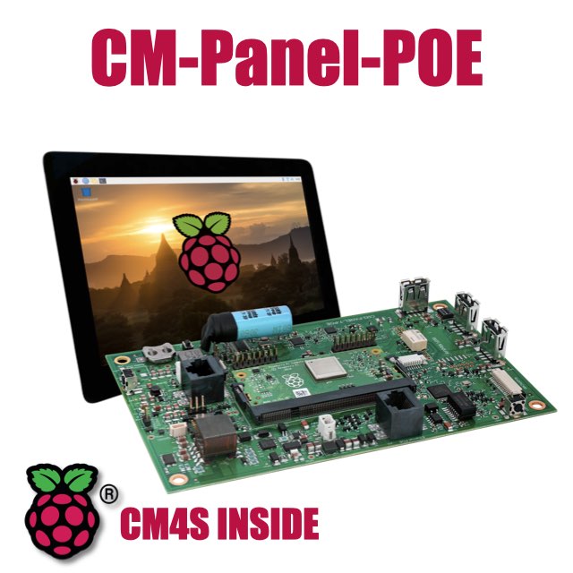
- 7 inch TFT display 800x480 pixel
- Capacitive touch
- Embedded micro UPS for safe shutdown
- Power Over Ethernet @ 10/100 Mbit
- Hi-resolution audio up to 384KHz@32bit
- Real Time Clock with backup battery
- 3 USB Host port
- 1 RS485/422/RS232 port
- 1 Relay
- MIPI Camera connector
- WiFi @ 2.4 GHz (optional)