CM Panel technical documentation Buy
How to manage the I2C buses on CM Panels
The I2C bus is used in the following ways on the two model of CM Panel available:
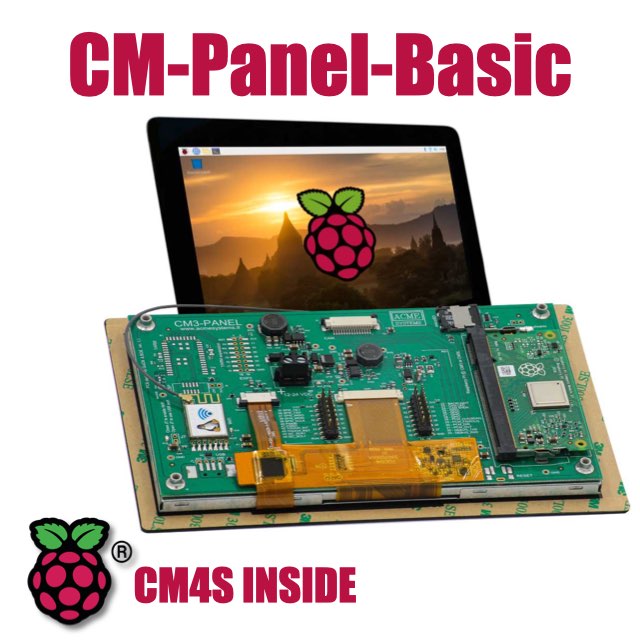
- CM-Panel BASIC
- Generic BUS on EXP1 connector
- Generic BUS on EXP2 connector
- Raspberry cam criptochip
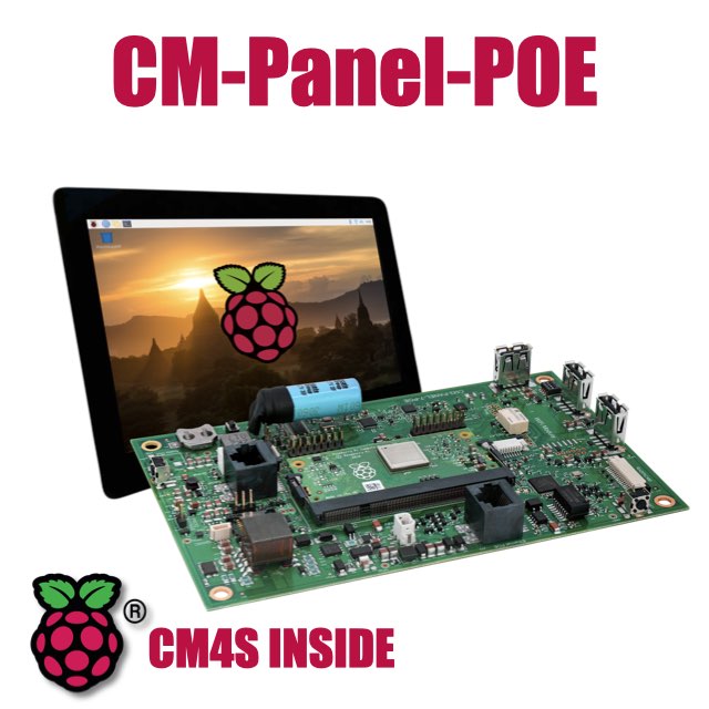
- CM-Panel POE
- Real Time Clock chip
- Acme sensor port
- Groove Seedstudio port
- QWIIC port
- Raspberry cam criptochip
I2C on EXP1 and EXP2 connectors onc CM-Panel BASIC
On the EXP1 and EXP2 connector of CM-Panel BASIC there are two I2C ports available for the user application
| EXP1 pin | Signal | Line |
|---|---|---|
| 11 | I2C SDA1 | GPIO 44 |
| 13 | I2C SCL1 | GPIO 45 |
| 16 | GND |
| EXP2 pin | Signal | Line |
|---|---|---|
| 15 | I2C SDA0 | GPIO 28 |
| 13 | I2C SCL0 | GPIO 29 |
| 16 | GND |
Enable the I2C ports
By default on the CM-Panel BASIC the I2C bus 1, available on GPIO 44 and 45 lines, is enabled just at Kernel level to comunicate with the touch panel and camera crypto chip.
This is done by modify the standard file config.txt as explained here:
The line used in the /boot/config.txt file is this:
dtoverlay=i2c1,pins_44_45
this setting is sufficient to enable I2C at the kernel call level. If you want to access I2C also from normal applications launched in user space, you need to enable the driver using the utility:
$ sudo raspi-config
and enable the port by following these options:
Interface Options -> I2C -> Would you like the ARM I2C interface to be enabled? YES
then reboot.
Install the i2c-tools to check the I2C bus from user space.
$ sudo apt update
$ sudo apt install i2c-tools
Type:
$ sudo i2cdetect -l
to see the logical devices to use in out applications
i2c-1 i2c bcm2835 (i2c@7e804000) I2C adapter
Type:
$ sudo i2cdetect -y 1
Result on CM-Panel BASIC will be:
     0  1  2  3  4  5  6  7  8  9  a  b  c  d  e  f
00:                         -- -- -- -- -- -- -- --
10: -- -- -- -- -- -- -- -- -- -- -- -- -- -- -- --
20: -- -- -- -- -- -- -- -- -- -- -- -- -- -- -- --
30: -- -- -- -- -- -- -- -- -- -- -- -- -- -- -- --
40: -- -- -- -- -- -- -- -- -- -- -- -- -- -- -- --
50: -- -- -- -- -- -- -- -- -- -- -- -- -- UU -- --
60: -- -- -- -- -- -- -- -- -- -- -- -- -- -- -- --
70: -- -- -- -- -- -- -- --
Result on CM-Panel POE will be:
     0  1  2  3  4  5  6  7  8  9  a  b  c  d  e  f
00:                         -- -- -- -- -- -- -- --
10: -- -- -- -- -- -- -- -- -- -- -- -- -- -- -- --
20: -- -- -- -- -- -- -- -- -- -- -- -- -- -- -- --
30: -- -- -- -- -- -- -- -- -- -- -- -- -- -- -- --
40: -- -- -- -- -- -- -- -- -- -- -- -- -- UU -- --
50: -- -- -- -- -- -- -- -- -- -- -- -- -- UU -- --
60: -- -- -- -- -- -- -- -- 68 -- -- -- -- -- -- --
70: -- -- -- -- -- -- -- --
The "UU" character displayed instead of the I2C address means that the chip is managed directly by a Kernel driver.
4Dis the Texas audio codec PCM51225Dis the Goodix touch controller chip68is the NXP Real Time Clock PCF8523 chip
Links
Products related
- 7 inch TFT display 800x480 pixel
- Capacitive touch
- Embedded micro UPS for safe shutdown
- Power Over Ethernet @ 10/100 Mbit
- Hi-resolution audio up to 384KHz@32bit
- Real Time Clock with backup battery
- 3 USB Host port
- 1 RS485/422/RS232 port
- 1 Relay
- MIPI Camera connector
- WiFi @ 2.4 GHz (optional)