# Pinout of EXP1 and EXP2 headers (CM-Panel BASIC)
On the bottom side of CM-Panel are available two sets of 16x2 pin strips pitch 2.54mm
where are available GPIOs, I2C buses, etc. This article explains how to use it
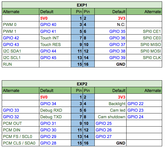
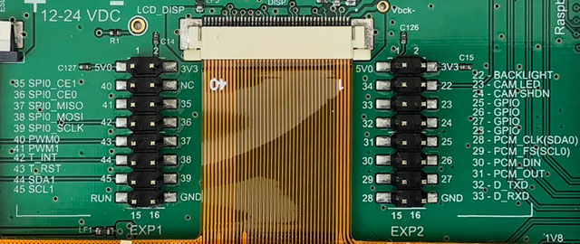 The number written near each pin on the silk screen indicates the GPIO number. The
pin numbering starts from top left down to bottom right.
On each pin group are available the power supply lines (+5 volt, +3.3 volt and GND)
and a set of GPIOs and control signals.
The number written near each pin on the silk screen indicates the GPIO number. The
pin numbering starts from top left down to bottom right.
On each pin group are available the power supply lines (+5 volt, +3.3 volt and GND)
and a set of GPIOs and control signals.
 ### Connectivity
To keep the price as low as possible the CM-Panel uses just the unique USB port available on the
Raspberry compute module to communicate with external devices.
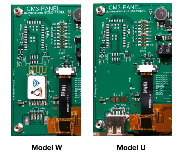
* On model "U" the Raspberry Compute Model USB port is available on a USB-A female connector. In this case the
connectivity can be make with an external USB adapter or using and USB HUB.
* On model "W" the Raspberry Compute Model USB port is used by a WiFi adapter. In this case no more USB device can be
connected to the CM-Panel.
The following photo shows the differences between the two models.
### Connectivity
To keep the price as low as possible the CM-Panel uses just the unique USB port available on the
Raspberry compute module to communicate with external devices.
* On model "U" the Raspberry Compute Model USB port is available on a USB-A female connector. In this case the
connectivity can be make with an external USB adapter or using and USB HUB.
* On model "W" the Raspberry Compute Model USB port is used by a WiFi adapter. In this case no more USB device can be
connected to the CM-Panel.
The following photo shows the differences between the two models.
 ### Debug port
Using an USB to serial interface it is possibile to access to the
debug port serial lines available on EXP2 connector as shown on this photo:
### Debug port
Using an USB to serial interface it is possibile to access to the
debug port serial lines available on EXP2 connector as shown on this photo:
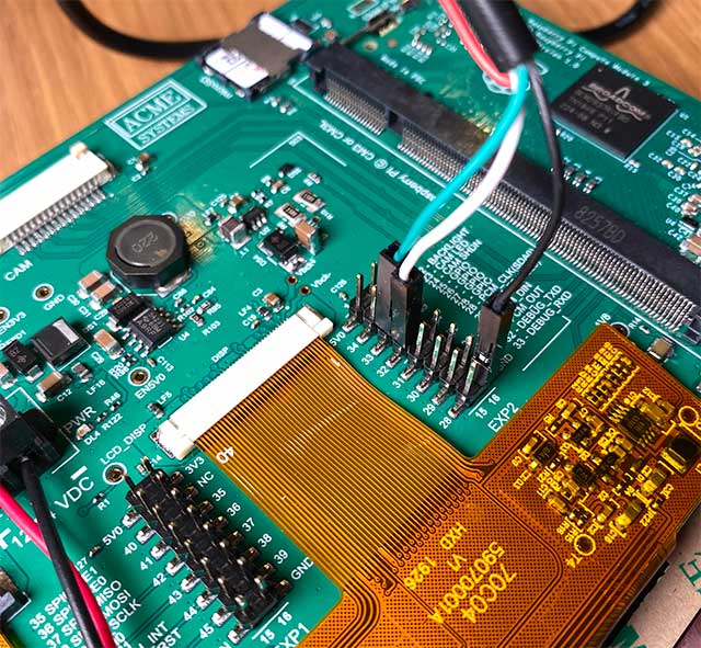 The lines used are:
| EXP2 pin | Signal |
|----------|---------------|
| GND | GND |
| 33 | Debug RX line |
| 32 | Debug TX line |
The serial setup is 11500,8,N,1
The lines used are:
| EXP2 pin | Signal |
|----------|---------------|
| GND | GND |
| 33 | Debug RX line |
| 32 | Debug TX line |
The serial setup is 11500,8,N,1