# Using up to 10 serial ports on RoadRunner SOM

<abstract>
On the Roadrunner is possible to use up to 9 serial ports for user purposes plus the debug serial port. 
This article illustrates how to activate at the same time all the ports available.
</abstract>

<a href="/roadrunner">
<img src="/photos/products_640/ROADRUNNER-Q16.jpg" height="240px" title="RoadRunner SOM">
</a>

<div class="alert alert-success" role="alert" markdown="1">
This article has been tried with a [Linux Kernel 4.19.134](/roadrunner_compile_kernel_4_19) and 
a [Debian Buster 10](/roadrunner_debos) distribution.
</div>

This is pheriperals available to implements the serial ports. When more IOset are listed the peripheral lines 
can be moved on another set of pins to avoid conflicts with other peripherals.

* UART0 (IOset1)
* UART1 (IOset1 or IOset2) (Used by default as debug port)
* UART2 (IOset1 or IOset2 or IOset3)
* UART3 (IOset1 or IOset3)
* UART4 (IOset1)
* FLEXCOM0 (IOset1)
* FLEXCOM1 (IOset1)
* FLEXCOM2 (IOset1 or IOset2)
* FLEXCOM3 (IOset1 or IOset2)
* FLEXCOM4 (IOset1)

To assign the /dev/ttySx device to each port use this alias list 
at the beginning of device tree file:

	aliases {
		serial0 = &uart1; /* /dev/ttyS0 Debug port */
		serial1 = &uart2; /* /dev/ttyS1            */
		serial2 = &uart3; /* /dev/ttyS2            */
		serial3 = &uart4; /* /dev/ttyS3            */
		serial4 = &uart0; /* /dev/ttyS4            */
		serial5 = &uart5; /* /dev/ttyS5            */
		serial6 = &uart6; /* /dev/ttyS6            */
		serial7 = &uart7; /* /dev/ttyS7            */
		serial8 = &uart8; /* /dev/ttyS8            */
		serial9 = &uart9; /* /dev/ttyS9            */
	};

### UART0

| Signal  | Dir | Description        | IOSet1       |
|---------|-----|--------------------|--------------|
| URXD0   | I   | Receive data       | PB26         |
| UTXD0   | O   | Transmit data      | PB27         |


	uart0: serial@f801c000 {
		pinctrl-names = "default";
		pinctrl-0 = <&pinctrl_uart0_ioset1>;
		status = "okay";
	};

	pinctrl@fc038000 {
		pinctrl_uart0_ioset1: uart0_ioset1 {
			pinmux = <PIN_PB26__URXD0>,
				 <PIN_PB27__UTXD0>;
			bias-disable;
		};
	};


### UART1 (Debug port)

| Signal  | Dir | Description        | IOSet1       |
|---------|-----|--------------------|--------------|
| URXD1   | I   | Receive data       | PD3          |
| UTXD1   | O   | Transmit data      | PD2          |


	uart1: serial@f8020000 {
		pinctrl-names = "default";
		pinctrl-0 = <&pinctrl_uart1_ioset1>;
		atmel,use-dma-rx;
		atmel,use-dma-tx;
		status = "okay";
	};

	pinctrl@fc038000 {
		pinctrl_uart1_ioset1: uart1_ioset1 {
			pinmux = <PIN_PD2__URXD1>,
				 <PIN_PD3__UTXD1>;
			bias-disable;
		};
	};

### UART2

| Signal  | Dir | Description        | IOSet1       |
|---------|-----|--------------------|--------------|
| URXD2   | I   | Receive data       | PD4          |
| UTXD2   | O   | Transmit data      | PD5          |

| Signal  | Dir | Description        | IOSet2       |
|---------|-----|--------------------|--------------|
| URXD2   | I   | Receive data       | PD23         |
| UTXD2   | O   | Transmit data      | PD24         |

| Signal  | Dir | Description        | IOSet3       |
|---------|-----|--------------------|--------------|
| URXD2   | I   | Receive data       | PD19         |
| UTXD2   | O   | Transmit data      | PD20         |


	uart2: serial@f8024000 {
		pinctrl-names = "default";
		pinctrl-0 = <&pinctrl_uart2_ioset1>;
		atmel,use-dma-rx;
		atmel,use-dma-tx;
		status = "okay";
	};


	pinctrl@fc038000 {
		pinctrl_uart2_ioset1: uart2_ioset1 {
			pinmux = <PIN_PD4__URXD2>,
				 <PIN_PD5__UTXD2>;
			bias-disable;
		};
		
		pinctrl_uart2_ioset2: uart2_ioset2 {
			pinmux = <PIN_PD23__URXD2>,
				 <PIN_PD24__UTXD2>;
			bias-disable;
		};
		
		pinctrl_uart2_ioset3: uart2_ioset3 {
			pinmux = <PIN_PD19__URXD2>,
				 <PIN_PD20__UTXD2>;
			bias-disable;
		};
	};

### UART3

| Signal  | Dir | Description        | IOSet1       |
|---------|-----|--------------------|--------------|
| URXD3   | I   | Receive data       | PC12         |
| UTXD3   | O   | Transmit data      | PC13         |

| Signal  | Dir | Description        | IOSet2       |
|---------|-----|--------------------|--------------|
| URXD3   | I   | Receive data       | PC31         |
| UTXD3   | O   | Transmit data      | PD0          |

| Signal  | Dir | Description        | IOSet3       |
|---------|-----|--------------------|--------------|
| URXD3   | I   | Receive data       | PB11         |
| UTXD3   | O   | Transmit data      | PB12         |

	uart3: serial@fc008000 {
		pinctrl-names = "default";
		pinctrl-0 = <&pinctrl_uart3_ioset1>;
		atmel,use-dma-rx;
		atmel,use-dma-tx;
		status = "okay";
	};


	pinctrl@fc038000 {
		pinctrl_uart3_ioset1: uart3_ioset1 {
			pinmux = <PIN_PC12__URXD3>,
				 <PIN_PC13__UTXD3>;
			bias-disable;
		};
		
		pinctrl_uart3_ioset2: uart3_ioset2 {
			pinmux = <PIN_PC31__URXD3>,
				 <PIN_PD0__UTXD3>;
			bias-disable;
		};
		
		pinctrl_uart3_ioset3: uart2_ioset3 {
			pinmux = <PIN_PB11__URXD3>,
				 <PIN_PB12__UTXD3>;
			bias-disable;
		};
	};

### UART4

| Signal  | Dir | Description        | IOSet1       |
|---------|-----|--------------------|--------------|
| URXD4   | I   | Receive data       | PB3          |
| UTXD4   | O   | Transmit data      | PB4          |


	uart4: serial@fc00C000 {
		pinctrl-names = "default";
		pinctrl-0 = <&pinctrl_uart4_ioset1>;
		status = "okay";
	};


	pinctrl@fc038000 {
		pinctrl_uart4_ioset1: uart4_ioset1 {
			pinmux = <PIN_PB3__URXD4>,
				 <PIN_PB4__UTXD4>;
			bias-disable;
		};
	};


### FLEXCOM0

| Signal       | Dir | Description        | IOSet1 |
|--------------|-----|--------------------|--------|
| FLEXCOM0_IO1 | I   | Receive data       | PB28   |
| FLEXCOM0_IO0 | O   | Transmit data      | PB29   |


	flx0: flexcom@f8034000 {
		atmel,flexcom-mode = <ATMEL_FLEXCOM_MODE_USART>;
		status = "okay"; 

		uart5: serial@200 {
			compatible = "atmel,at91sam9260-usart";
			reg = <0x200 0x200>;
			interrupts = <19 IRQ_TYPE_LEVEL_HIGH 7>;
			clocks = <&flx0_clk>;
			clock-names = "usart";
			pinctrl-names = "default";
			pinctrl-0 = <&pinctrl_flx0_ioset1>;
			atmel,fifo-size = <32>;
			status = "okay";
		};
	};

TX and RX lines 

	pinctrl@fc038000 {
		pinctrl_flx0_default: flx0_ioset1 {
			pinmux = <PIN_PB28__FLEXCOM0_IO0>, /* TX */
					 <PIN_PB29__FLEXCOM0_IO1>; /* RX */
			bias-disable;
		};
	};

TX and RX lines plus CTS and RTS

	pinctrl@fc038000 {
		pinctrl_flx0_default: flx0_ioset1 {
			pinmux = <PIN_PB28__FLEXCOM0_IO0>, /* TX */
					 <PIN_PB29__FLEXCOM0_IO1>, /* RX */
					 <PIN_PB31__FLEXCOM0_IO3>,
					 <PIN_PC0__FLEXCOM0_IO4>;
			bias-disable;
		};
	};

### FLEXCOM1

| Signal       | Dir | Description        | IOSet1 |
|--------------|-----|--------------------|--------|
| FLEXCOM1_IO1 | I   | Receive data       | PA23   |
| FLEXCOM1_IO0 | O   | Transmit data      | PA24   |


	flx1: flexcom@f8038000 {
		atmel,flexcom-mode = <ATMEL_FLEXCOM_MODE_USART>;
		status = "okay"; 

		uart6: serial@200 {
			compatible = "atmel,at91sam9260-usart";
			reg = <0x200 0x200>;
			interrupts = <20 IRQ_TYPE_LEVEL_HIGH 7>;
			clocks = <&flx1_clk>;
			clock-names = "usart";
			pinctrl-names = "default";
			pinctrl-0 = <&pinctrl_flx1_ioset1>;
			atmel,fifo-size = <32>;
			status = "okay";
		};
	};

	pinctrl@fc038000 {
		pinctrl_flx1_ioset1: flx1_ioset1 {
			pinmux = <PIN_PA24__FLEXCOM1_IO0>,
				 <PIN_PA23__FLEXCOM1_IO1>;
			bias-disable;
		};
	};
	

### FLEXCOM2

| Signal       | Dir | Description        | IOSet1 |
|--------------|-----|--------------------|--------|
| FLEXCOM2_IO1 | I   | Receive data       | PA27   |
| FLEXCOM2_IO0 | O   | Transmit data      | PA26   |

	flx2: flexcom@fc010000 {
		atmel,flexcom-mode = <ATMEL_FLEXCOM_MODE_USART>;
		status = "okay";

		uart7: serial@200 {
			compatible = "atmel,at91sam9260-usart";
			reg = <0x200 0x200>;
			interrupts = <21 IRQ_TYPE_LEVEL_HIGH 7>;
			clocks = <&flx2_clk>;
			clock-names = "usart";
			pinctrl-names = "default";
			pinctrl-0 = <&pinctrl_flx2_ioset1>;
			atmel,fifo-size = <32>;
			status = "okay";
		};
	};

	pinctrl@fc038000 {
		pinctrl_flx2_ioset1: flx2_ioset1 {
			pinmux = <PIN_PD26__FLEXCOM2_IO0>,
				 <PIN_PD27__FLEXCOM2_IO1>;
			bias-disable;
		};
	};

### FLEXCOM3

| Signal       | Dir | Description        | IOSet1 |
|--------------|-----|--------------------|--------|
| FLEXCOM3_IO1 | I   | Receive data       | PA13   |
| FLEXCOM3_IO0 | O   | Transmit data      | PA15   |

	flx3: flexcom@fc014000 {
		atmel,flexcom-mode = <ATMEL_FLEXCOM_MODE_USART>;
		status = "okay";

		uart8: serial@200 {
			dmas = <0>, <0>;
			compatible = "atmel,at91sam9260-usart";
			reg = <0x200 0x200>;
			interrupts = <22 IRQ_TYPE_LEVEL_HIGH 7>;
			clocks = <&flx3_clk>;
			clock-names = "usart";
			pinctrl-names = "default";
			pinctrl-0 = <&pinctrl_flx3_ioset1>;
			atmel,fifo-size = <32>; 
			status = "okay"; 
		};
	};

	pinctrl@fc038000 {
		pinctrl_flx3_ioset1: flx3_ioset1 {
			pinmux = <PIN_PA15__FLEXCOM3_IO0>,
				 <PIN_PA13__FLEXCOM3_IO1>;
			bias-disable;
		};
	};

### FLEXCOM4

| Signal       | Dir | Description        | IOSet1 |
|--------------|-----|--------------------|--------|
| FLEXCOM4_IO1 | I   | Receive data       | PC29   |
| FLEXCOM4_IO0 | O   | Transmit data      | PC28   |

	flx4: flexcom@fc018000 {
		atmel,flexcom-mode = <ATMEL_FLEXCOM_MODE_USART>;
		status = "okay";
	
		uart9: serial@200 {
			compatible = "atmel,at91sam9260-usart";
			reg = <0x200 0x200>;
			interrupts = <23 IRQ_TYPE_LEVEL_HIGH 7>;
			clocks = <&flx4_clk>;
			clock-names = "usart";
			pinctrl-names = "default";
			pinctrl-0 = <&pinctrl_flx4_ioset1>;
			atmel,fifo-size = <32>;
			status = "okay"; 
		};
	};

	pinctrl@fc038000 {
		pinctrl_flx4_ioset1: flx4_ioset1 {
			pinmux = <PIN_PC28__FLEXCOM4_IO0>,
				 <PIN_PC29__FLEXCOM4_IO1>;
			bias-disable;
		};
	};

## Check the serial devices

<div class="terminal">
	ls -al /dev/ttyS*
	
	crw------- 1 root tty     4, 64 Jul 28 10:22 /dev/ttyS0
	crw-rw---- 1 root dialout 4, 65 Jul 28 09:10 /dev/ttyS1
	crw-rw---- 1 root dialout 4, 66 Jul 28 09:10 /dev/ttyS2
	crw-rw---- 1 root dialout 4, 67 Jul 28 09:10 /dev/ttyS3
	crw-rw---- 1 root dialout 4, 68 Jul 28 09:10 /dev/ttyS4
	crw-rw---- 1 root dialout 4, 69 Jul 28 09:10 /dev/ttyS5
	crw-rw---- 1 root dialout 4, 70 Jul 28 09:10 /dev/ttyS6
	crw-rw---- 1 root dialout 4, 71 Jul 28 09:10 /dev/ttyS7
	crw-rw---- 1 root dialout 4, 72 Jul 28 09:10 /dev/ttyS8
	crw-rw---- 1 root dialout 4, 73 Jul 28 09:10 /dev/ttyS9	
</div>
	
Install minicon

<div class="terminal">
	sudo apt update
	sudo apt install -y minicom
</div>

To use minicom be shure to don't use the Roadrunner debug port from your PC to avoid strange behaviour. 
Use a ssh remote session instead

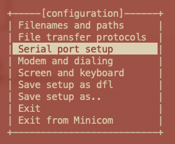
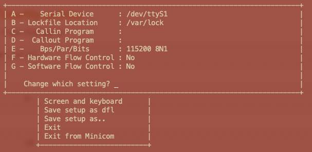
Launch and select for example the port /dev/ttyS1

<div class="terminal">
	sudo minicom -s
</div>
	
Select: 
	
<img src="./select_serial_port.png">
	
then set:

<img src="./serial_setup.png">

wire together the lines PB27 (TXD0) and PB26 (RXD0) to do an hardware loopback the
type some characters on minicom to see if it works


## Change the limit on /dev/tty entries

To enable more than 8 serial lines change in: 

	drivers/tty/serial/atmel_serial.c 

the line:

	#define ATMEL_MAX_UART		8

in: 

	#define ATMEL_MAX_UART		10
	
## A ready-to-use device tree source

* [acme-roadrunner-10uart.dts](https://github.com/AcmeSystems/dts-archive/blob/master/4.19/acme-roadrunner-10uart.dts)
	
## Links

* [How to compile the Linux Kernel and Device tree](/roadrunner_compile_kernel_4_19)
* @article='serial'
 
@include='adv_roadrunner'