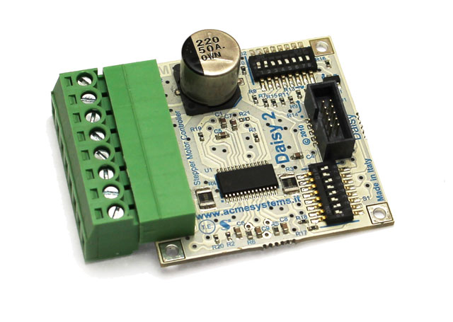
DAISY-2 - Stepper motor driver board
DAISY-2 module gives all the functions provided by the Texas chip adding a low-power feature which allows to keep the stepper motor in torque with a low current consumption configurable by dip-switches.
|
Main features
|
Internal shutdown functions are provided for over current protection, short circuit protection, under-voltage lockout and overtemperature
Control GPIO lines required:
Up to 4 GPIO lines are used by the DAISY-2 module from daisy connector:
- Enable
- Step
- Dir
- Low power
Wirings
These are the usable connectors where to plug this board using the factory default Linux Kernel image:
| Terra | FOXG20 |
|---|---|
| D11 | D1 |
| D12 | D6 |
| D8 |
On the FOX Board G20 is requested a Daisy-1 adapter to wire this boards.
Pin map
|
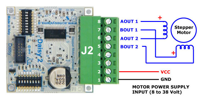
J2 pin-out
|
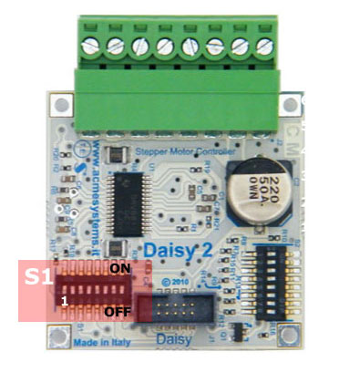
S1 dip-switch description
|
The S1 dip-switch selects which GPIO incoming lines link to the following DAISY-2 control
signals:
Only four GPIO lines incoming from the CPU are used by the DAISY-2 module to control the stepper motor. Configuring the S1 dip-switch it is possible to select whether to use odd or even wires available on the Daisy connector. We simply call this configurations A and B. Configurations A and B are useful if you need to place two DAISY-7 modules on a same flat cable. Setting A on the first board and B on the second one it is possible to control up to four DAISY-2 modules using just D2 and D5 daisy connector.
Please be careful to use only these two dip-switch configuration to avoid shortcuts between GPIO lines. Following are the kernel GPIO IDs used when the DAISY-2 module is plugged on D2 or D5 daisy connectors on a DAISY-1 interface.
|
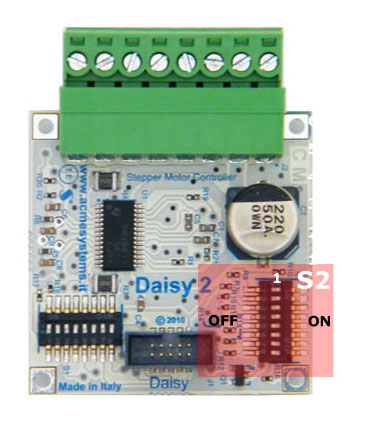
S2 dip-switch description
|
The S2 dip-switch allow you to choice the micro-stepping value and motor current for both normal and low-power mode.
Lowpower operation is a feature that can be enable via software and is useful to maintain the to motor axis in torsion without overheat the internal coils. USM0 and USM1 dip switch selected micro stepping mode. Refer to page # 12 on Texas DRV8811 datasheet for in-deep info.
The other dip-switches can be used to set-up the motor current and the low power condition.
If DIP 6,7 and 8 are all OFF the low power function is disable by hardware. (1) normal current, calculated value
|
Examples in Python
The following examples use: the soft_pwm kernel driver module written by Antonio Galea.
- Follow this article: A kernel module for generating bit banging PWM signals
to install it on your acme board.
They use also the ablib Python module available in the playground examples collection.
Example #1 - Move one stepper motor
Basic example which move the stepper motor 360� in clockwise direction then 360� in anti-clockwise direction.
Hardware set-up
Plug the DAISY-2 module on D5 connector on DAISY-1 module then set up the S1 dip-switches in configuration A
| 1 | 2 | 3 | 4 | 5 | 6 | 7 | 8 | |
|---|---|---|---|---|---|---|---|---|
| Configuration A | ON | ON | ON | ON |
Set all the S2 dip-switches in state ON to set-up the full-step mode (usually 200 step for 360 degree) using a minimal current.
Wire your steper motor as explained below in the Stepper motor wirings section then run the Python example.
Example #2 - Move two stepper motors
Simple example which move two stepper motors 360� in clockwise direction then 360� in anti-clockwise direction.
Hardware set-up
Plug one DAISY-2 module on D2 connector on DAISY-1 module then set up the S1 dip-switches in configuration A
| 1 | 2 | 3 | 4 | 5 | 6 | 7 | 8 | |
|---|---|---|---|---|---|---|---|---|
| Configuration A | ON | ON | ON | ON |
Plug another DAISY-2 module on D5 connector on DAISY-1 module then set up the S1 dip-switches in configuration B
| 1 | 2 | 3 | 4 | 5 | 6 | 7 | 8 | |
|---|---|---|---|---|---|---|---|---|
| Configuration B | ON | ON | ON | ON |
Set all the S2 dip-switches in state ON to set-up the full-step mode (usually 200 step for 360 degree) using a minimal current.
Wire your steper motor as explained below in the Stepper motor wirings section the run the Python example.
Example #3 - Move 8 stepper motors
Demo to show you how to manage the max number of stepper motor with one FOX Board G20.
To use this example you have to disable some interface on Linux Kernel:
- 1-wire bus on D2 daisy connector
- ttyS1 serial line on D3 daisy connector
- ttyS4 and I2C on D6 daisy connector
- SPI bus on D7 daisy connector
Here is the modified board-foxg20.c source.
Hardware set-up
Plug 8 DAISY-2 modules in this way:
| Daisy connector | Daisy-2 configuration |
|---|---|
| D2 | A |
| D2 | B |
| D3 | A |
| D3 | B |
| D5 | A |
| D5 | B |
| D6 | A |
| D7 | A |
Run the Python example.
Stepper motor wirings
We tested the examples on this article with the following stepper motors:
Mercury NEMA-17 stepper motor SM-42BYG011-25
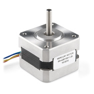
Wirings map:
| J2 pins on DAISY-2 | Mercury wire colors | Function description |
|---|---|---|
| 1 | GND power supply | |
| 2 | VCC (12 volt) power supply | |
| 5 | BLUE | Bridge B output 2 |
| 6 | GREEN | Bridge A output 2 |
| 7 | YELLOW | Bridge B output 1 |
| 8 | RED | Bridge A output 1 |
Wantai NMEA-23 stepper motor 57BYG621
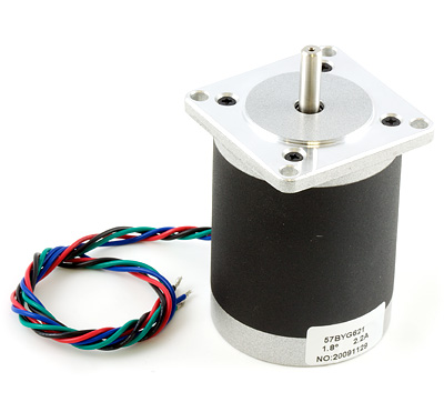
Wirings map:
| J2 pins on DAISY-2 | Wantai wire colors | Function description |
|---|---|---|
| 1 | GND power supply | |
| 2 | VCC (12 volt) power supply | |
| 5 | BLUE | Bridge B output 2 |
| 6 | GREEN | Bridge A output 2 |
| 7 | RED | Bridge B output 1 |
| 8 | BLACK | Bridge A output 1 |