DAISY-22 - I2C bus 8 channel I/O expander


DAISY-22 is pluggable to the Daisy conectors D1, D6 and D8 (see DAISY-1 board) sharing the same I2C bus. Alternatively up to 8 module can be plugged on a single flat cable.
The voltage level on GPIO are configurable at 3.3 volt or 5 volt via dip switches
Other features:
- Low current consumption
- Latched outputs
- High current drive capability for directly driving LEDs
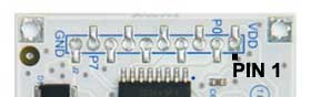
GPIO pinout
8 general purpose I/O lines and 3.3 or 5 volt power lines are available on pitch 2.54mm pads as shown below:
| Pin | Signal | Description |
|---|---|---|
| 1 | VDD | Power line out. It could be at 3.3 or 5 volt |
| 2 | P0 | General purpose I/O line |
| 3 | P1 | General purpose I/O line |
| 4 | P2 | General purpose I/O line |
| 5 | P3 | General purpose I/O line |
| 6 | P4 | General purpose I/O line |
| 7 | P5 | General purpose I/O line |
| 8 | P6 | General purpose I/O line |
| 9 | P7 | General purpose I/O line |
| 10 | GND | GND power line |
It is possible to set the operating voltage level and power line at 3.3 volt or 5 volt using the on-board dip switch.
Dip-switch configuration
With the dip switch on-board it is possible to select which is the I2C address assigned in the range of 20 hex to 27 hex, where is wired the PCF8574 interrupt pin and the GPIO voltage level.

This is the meaning of each dip switch:
| Dip # | Function |
|---|---|
| 1 | A0 - I2C address |
| 2 | A1 - I2C address |
| 3 | A2 - I2C address |
| 4 | ON = PCF8574 IRQ out on pin 3 |
| 5 | ON = PCF8574 IRQ out on pin 4 |
| 6 | ON = PCF8574 IRQ out on pin 5 |
| 7 | ON = PCF8574 IRQ out on pin 6 |
| 8 | ON = VDD 5 volt | OFF = VDD 3.3 volt |
I2C bus address setup
This is the setup configuration for dip 1,2 and 3 to assign the I2C address to the module:
| A0 (DIP1) | A1 (DIP2) | A2 (DIP3) | I2C chip address |
|---|---|---|---|
| ON | ON | ON | 0x20 |
| OFF | ON | ON | 0x21 |
| ON | OFF | ON | 0x22 |
| OFF | OFF | ON | 0x23 |
| ON | ON | OFF | 0x24 |
| OFF | ON | OFF | 0x25 |
| ON | OFF | OFF | 0x26 |
| OFF | OFF | OFF | 0x27 |
Note: Before starting your experiments be sure to select the right voltage levels for the GPIO port and VDD power line using the dip switch # 8. This is very important to avoid damage to the external hardware wired on the DAISY-22 board.
Python examples
pulse.py Use the expander GPIO line as output
readline.py Use the expander GPIO line as input
Use DAISY-22 with legacy kernel
By default you can communicate with the DAISY-22 using legacy user-space tool over the i2c device.
Extend the gpio kernel api
You will probably want to extend the standalone gpio interface with this new 5V enable interface. Fortunately this is very simple you should only enable the PCF85XX driver inside your kernel Image and add the correct i2c address to the board definition.
This will result in a new gpiochip that can be controlled with the standard GPIO api, including the sysfs utility.
Inside foxg20 board definition you should add a new i2c chip as follows:
static struct i2c_board_info __initdata foxg20_i2c_devices[] = {
    {
        I2C_BOARD_INFO("24c512", 0x50),
    },
    // First line to be added
    {
        I2C_BOARD_INFO("pcf8574a", 0x27), //change the slave addr (0x27) appropriately
    },
    {
        I2C_BOARD_INFO("pcf8574a", 0x20), //register a second chip on different slave addr
    },
    // Last line added
};
Then enable the kernel symbol CONFIG_GPIO_PCF857X inside kernel config.
Symbol: GPIO_PCF857X [=y]
    Type  : tristate
    Prompt: PCF857x, PCA{85,96}7x, and MAX732[89] I2C GPIO expanders
      Defined at drivers/gpio/Kconfig:191
      Depends on: GPIOLIB [=y] && I2C [=y]
      Location:
        -> Device Drivers
          -> GPIO Support (GPIOLIB [=y])
      Selected by: MACH_DAVINCI_DA830_EVM [=n] && ARCH_DAVINCI [=n] && ARCH_DAVINCI_DA830 [=n]
Once the kernel is installed and running you can find a new gpiochip inside your system. A gpiochip is the gpio controller representation inside the kernel (read more inside kernel documentation). This gpiochip is basically an enumerator for each real GPIO under its control. Our aim is to find the base integer that is dynamically assigned to the gpiochip at boot time and then use it as base-number to enumerate the eight DAISY-22 pins in sequence.
For example if you have a single DAISY-22 you can read inside dmesg something like:
debarm:~# dmesg
...
i2c-gpio i2c-gpio: using pins 55 (SDA) and 56 (SCL)
i2c /dev entries driver
...
pcf857x 0-0027: gpios 248..255 on a pcf8574
...
This means that GPIO 248 is DAISY-22.P0 up to GPIO 255 for DAISY-22.P7. Otherwire in /sys/class/gpio/ you can find a directory called gpiochip248
debarm:~# ls /sys/class/gpio/gpiochip248
base  device  label  ngpio  power  subsystem  uevent
debarm:~# cat /sys/class/gpio/gpiochip248/label
pcf8574
debarm:~# cat /sys/class/gpio/gpiochip248/ngpio
8
Now you can use the classic sysfs method to managed GPIO interface or use it inside kernel driver.
Schematics, datasheets and related links
Errata corrige
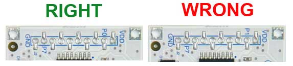
On the first production batch of DAISY-22 the pad names P1 and P7 on the silk screen could be wrong. The right labels are P0 and P7 as as seen in the figure below. On some boards it has been corrected by hand.