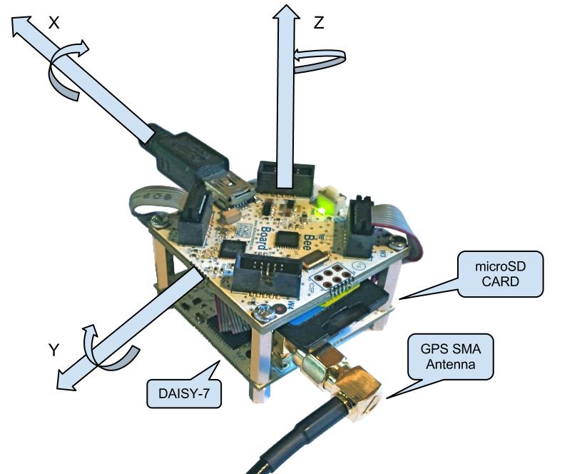
BEE Board and Daisy-7 IMU-GPS module
Create your IMU inertial measurement Application in small area
This article illustrate how to read all values from Daisy-7 with BEE Board.
This module extends the BEE Board capabilities to make GPS/MEMS applications such as
- Motion activated functions
- Intelligent power saving for handheld devices
- Appliances and robotics
- Motion Control
- IMU inertial measurement unit & AHRS
- GPS tracking
- Black box
- Motion reconstruction and analysis
Application example : BlackBox
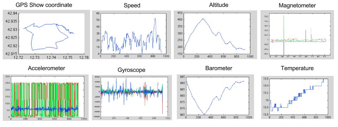
Dump DAISY-7 data in CSV file for motion reconstruction and analysis.
This example executes a dump of all data received from the DAISY-7 every 200ms on a micro SD card. We are connected one button and one led for user interface. Press button to start logging, every led blink one row are recorded in CSV file. If you hold button on startup, dump file is emptied!
To connect SD Card to W3 of BEE Board follow this guide
Data collected from my BlackBox
Hardware Required
BEE Board Code
BlackBox.ino
Matlab import and plot CSV dump file
plotData.m
importCSV.m
Application example : GPS Tracking with SMS
Tracking your mobile application with SMS
![]()
Hardware Required
In this example if a number stored in SIM Phone Book calls Daisy-13, it responds with GPS coordinate in SMS.
For more info about Daisy-13 and BEE Board, follow this page
Code
TrackerGPS.ino
Library to manage Daisy-7 with BEE Board
Communication
- GPS communicate via Serial Port at 115200 baudrate.
- Other sensor communicate via I2C bus.
This scenario is optimal for W1 :)
Daisy7 library
- Download and Install it by following this guide.
- Plug Ribble Cable on Wings W1
- open IDE and iclude Dasiy7 Library.
Related links
