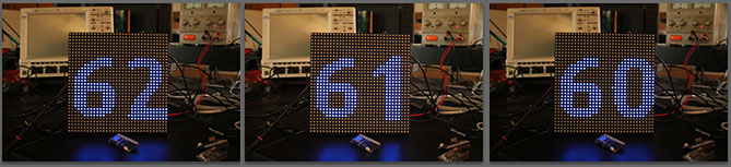
~/led-utils# ./counter.pySource code: [counter.py](https://github.com/tanzilli/led-utils/blob/master/counter.py)
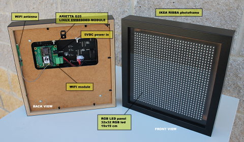 The whole project is based on the full color RGB led panel made by
the Chinese company
Linsn.
It is composed by 1024 rgb led ordered in 32 rows of 32 leds each and mounted with a lot of logic
on a black PCB 19x19 cm size. Everything in enclosed in a plastic frame with a set on placement
for M3 screws to use for mounting.
The cost of creating a panel like this for an European company could be around 200 eur just for manufacturing
and components so the best thing to do is to buy it :-)
The whole project is based on the full color RGB led panel made by
the Chinese company
Linsn.
It is composed by 1024 rgb led ordered in 32 rows of 32 leds each and mounted with a lot of logic
on a black PCB 19x19 cm size. Everything in enclosed in a plastic frame with a set on placement
for M3 screws to use for mounting.
The cost of creating a panel like this for an European company could be around 200 eur just for manufacturing
and components so the best thing to do is to buy it :-)
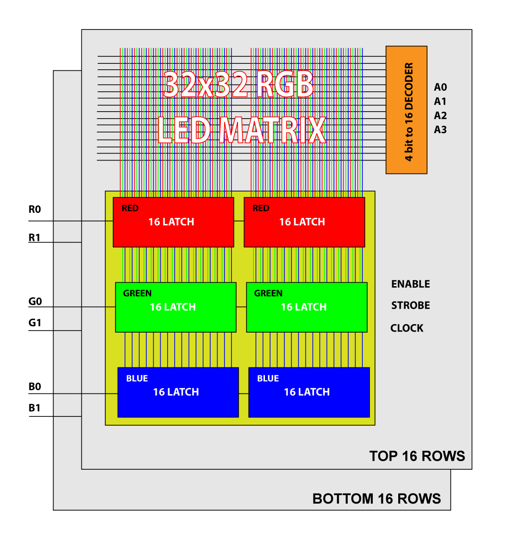
 The datasheet of this panel with a correct explanation about how it works is not easily available.
In this page I'll try to explain how "it seems to work" :-)
On the rear an Arietta G25 module is used to generate all the
signals requested by the RGB panel starting from a 32x32 pixel graphic image.
The Pyhton graphic library called Pillow
is used to create the image starting from graphic primitives, true type fonts, and jpg, png, etc images.
The WiFi capability of the Arietta G25 (also in Access Point mode) and the Python module for
the networking, open a lot of possible uses of this project.
Linux is loaded in few seconds from an 8GB microSD with more than 7.8 GB free !!
Tons of softwares, tools, languages and libraries can be installed. Complete step by step guides
are available on this site.
###Software used
The datasheet of this panel with a correct explanation about how it works is not easily available.
In this page I'll try to explain how "it seems to work" :-)
On the rear an Arietta G25 module is used to generate all the
signals requested by the RGB panel starting from a 32x32 pixel graphic image.
The Pyhton graphic library called Pillow
is used to create the image starting from graphic primitives, true type fonts, and jpg, png, etc images.
The WiFi capability of the Arietta G25 (also in Access Point mode) and the Python module for
the networking, open a lot of possible uses of this project.
Linux is loaded in few seconds from an 8GB microSD with more than 7.8 GB free !!
Tons of softwares, tools, languages and libraries can be installed. Complete step by step guides
are available on this site.
###Software used
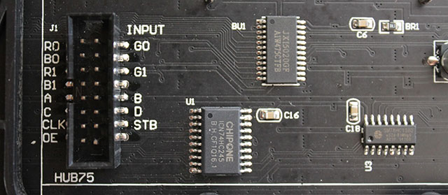
 ##Pinout
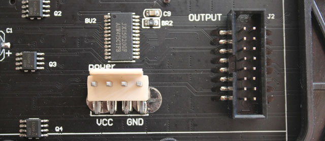
This is the pinout of input data connector:
##Pinout
This is the pinout of input data connector:
 | LED Pin # | Signal | Description | Arietta pin # | Line | gpio ID |
|-----------|--------|----------------|---------------|------|---------|
| 1 | R0 | Red 1st bank | J4.10 | PA21 | 21 |
| 2 | G0 | Green 1st bank | J4.8 | PA22 | 22 |
| 3 | B0 | Blue 1st bank | J4.7 | PA23 | 23 |
| 4 | GND | Ground | J4.9 | | |
| 5 | R1 | Red 2nd bank | J4.11 | PA24 | 24 |
| 6 | G1 | Green 2nd bank | J4.13 | PA25 | 25 |
| 7 | B1 | Blue 2nd bank | J4.15 | PA26 | 26 |
| 8 | GND | Ground | J4.9 | | |
| 9 | A | Row address | J4.28 | PA5 | 5 |
| 10 | B | Row address | J4.27 | PA6 | 6 |
| 11 | C | Row address | J4.26 | PA7 | 7 |
| 12 | D | Row address | J4.25 | PA8 | 8 |
| 13 | CLK | Clock | J4.17 | PA27 | 27 |
| 14 | STB | Strobe | J4.19 | PA28 | 28 |
| 15 | OE | Output Enable | J4.21 | PA29 | 29 |
| 16 | GND | Ground | J4.9 | | |
| LED Pin # | Signal | Description | Arietta pin # | Line | gpio ID |
|-----------|--------|----------------|---------------|------|---------|
| 1 | R0 | Red 1st bank | J4.10 | PA21 | 21 |
| 2 | G0 | Green 1st bank | J4.8 | PA22 | 22 |
| 3 | B0 | Blue 1st bank | J4.7 | PA23 | 23 |
| 4 | GND | Ground | J4.9 | | |
| 5 | R1 | Red 2nd bank | J4.11 | PA24 | 24 |
| 6 | G1 | Green 2nd bank | J4.13 | PA25 | 25 |
| 7 | B1 | Blue 2nd bank | J4.15 | PA26 | 26 |
| 8 | GND | Ground | J4.9 | | |
| 9 | A | Row address | J4.28 | PA5 | 5 |
| 10 | B | Row address | J4.27 | PA6 | 6 |
| 11 | C | Row address | J4.26 | PA7 | 7 |
| 12 | D | Row address | J4.25 | PA8 | 8 |
| 13 | CLK | Clock | J4.17 | PA27 | 27 |
| 14 | STB | Strobe | J4.19 | PA28 | 28 |
| 15 | OE | Output Enable | J4.21 | PA29 | 29 |
| 16 | GND | Ground | J4.9 | | |
~# git clone git://github.com/tanzilli/led-utils.git
Cloning into 'led-utils'...
remote: Counting objects: ..., done.
remote: Compressing objects: 100% (../..), done.
Receiving objects: 100% ..., done.
Resolving deltas: 100% ..., done.
~# cd led-utils
~/led-utils# ./clock-py
###Install PIL All the utilities use the Python Interface Library to manage images, font, etc so before trying any example install PIL on your Arietta G25 by typing:
# apt-get update
# apt-get install python-imaging
This is the list of utilities available. If you can't run something try to update your repository by typing: __git pull__. ##Demo gallery ### Example: Simple 2 digit countdown counter
This example written in Python shows a count down from 99 to 0 using a full size TTF font.### Example: Sliding messages~/led-utils# ./counter.pySource code: [counter.py](https://github.com/tanzilli/led-utils/blob/master/counter.py)
This example, written in Python, shows a sliding message using a big TTF font The RGB color and the message to display are given from the command line.### Example: Sliding clock This example shows the system time in HH:MM:SS format using a big TTF font and slide the line horizontaly.~/led-utils# ./text.py "text" R G BThe R, G and B values are in range of 0 (off) to 7 (max) Source code: [text.py](https://github.com/tanzilli/led-utils/blob/master/text.py)
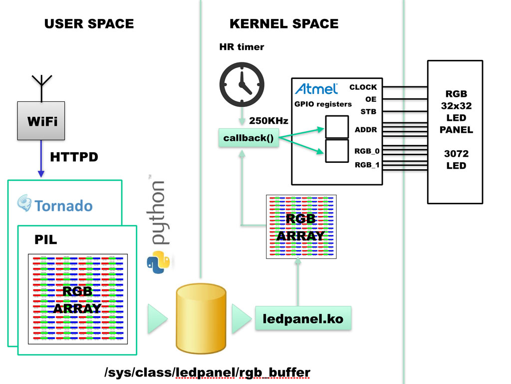
The RGB color is given from the command line.##The Linux driver ledpanel.c All the rgb led panel are generate in bit banging mode using normal GPIO lines. To go as fast as possible a Linux driver written in C code is required. The driver I wrote can update the whole panel contents 679 times per second leaving enough time to Linux to do other jobs in the meanwhile. The main routine of this driver is a callback function called by a hrtimer 10800 times per second at interval of 92uS. In just 22uS this routine check the brightness of each color and send a simulated pwm signal to any led (32 x 3 color = 96) on a single row then exit. It will be called again by the Kernel after 66uS. The fully source code of this driver is available under GPL licence on GitHub: [ledpanel source on GitHub](https://github.com/tanzilli/ledpanel/blob/master/ledpanel.c) ###How the driver works~/led-utils# ./clock.py R G BThe R, G and B values are in range of 0 (off) to 7 (max) Source code: [clock.py](https://github.com/tanzilli/led-utils/blob/master/clock.py) Is available a demo version of this programm called __clock_demo.py__ which changes automatically the colors during the time sliding:~/led-utils# ./clock_demo.pySource code: [clock_demo.py](https://github.com/tanzilli/led-utils/blob/master/clock_demo.py)
General setup  --->
	Timers subsystem  --->
		[*] High Resolution Timer Support
Clone the GitHub repository on your Linux PC:
$ git clone git://github.com/tanzilli/ledpanel.git
$ cd ledpanel
~/ledpanel$
Compile the module by typing:
~/ledpanel$ make -C ~/arietta/linux-4.1.10 ARCH=arm CROSS_COMPILE=arm-linux-gnueabi- M=`pwd` modulesand copy in inside Arietta G25
~/ledpanel$ sshpass -p acmesystems scp ledpanel.ko root@192.168.10.10:/rootOpen a command session on Arietta and load the Kernel module:
root@arietta:~# insmod ledpanel.koNow you can try some example to show something on the display.
$ tar -xvjpSf boot.tar.bz2 -C /media/$USER/boot
$ sudo tar -xvjpSf rootfs.tar.bz2 -C /media/$USER/rootfs
* unmount the microsd and try it on your Arietta ###Login data * Login: root Password: acmesystems ###How to use Access to WiFi LedPanel and go to these address from your browser: * [http://192.168.0.1](http://192.168.0.1)