GPIO General purpose I/O
written by Sergio Tanzilli, Roberto AsquiniAn introduction to the GPIO available on the J6 and J7 extension sockets
The microprocessor ETRAX 100LX used on the FOX Board has 3 general I/O port registers:
- Port A is an 8 bit register
- Port B is an 8 bit register
- Port G is a 32 bit register
For each bit inside these three registers, there are one or more related physical lines on the J6 and J7 extension sockets of the FOX Board.
Some of these lines can work only as input lines (i.e. IGx lines) or as output lines (i.e. OGx lines), others can work in bidirectional mode (i.e. IOGx, PA and PB lines). Not the all 8 + 8 + 32 = 48 bits are available as general input/output lines at the same time. Some of these are shared with other internal devices of the ETRAX CPU like serial asynchronous lines, IDE bus, I2C etc.
The factory default configuration of the I/O lines are listed below. The general I/O lines available are signed in green.
Port AA0 J7.38 (I/O) O General purpose I/O line A1 J7.37 (I/O) I On board switch SW1 A2 J7.36 (I/O) O On board led DL2 A3 J7.35 (I/O) O On board led DL1 A4 J7.34 (I/O) O DTR line on /dev/ttyS2 A5 J7.33 (I/O) I RI line on /dev/ttyS2 A6 J7.32 (I/O) I DSR line on /dev/ttyS2 A7 J7.31 (I/O) I CD line on /dev/ttyS2 Port BB0 J6.32 (I/O) ? I2C_DATA line B1 J6.31 (I/O) O I2C_CLOCK line B2 J6.34 (I/O) O VPO line on USB1 B3 J6.33 (I/O) O VMO line on USB1 B4 J6.36 (I/O) I General purpose I/O line B5 J6.35 (I/O) I VM line on USB1 B6 J6.38 (I/O) O General purpose I/O line B7 J6.37 (I/O) O General purpose I/O line Port GIOG0 J7.22 (I/O) O General purpose I/O line IG1 J6.24 (I) I General purpose input line IG2 J6.29 (I) I General purpose input line IG3 J6.28 (I) I General purpose input line IG4 J6.27 (I) I General purpose input line IG5 J6.30 (I) I General purpose input line IG6 J6.8 (I) I RXD line on /dev/ttyS2 IG7 J6.10 (I) I CTS line on /dev/ttyS2 OG1 J6.23 (O) O General purpose output line OG2 J6.21 (O) O I2C RESET line OG3 J6.26 (O) O General purpose output line OG4 J6.25 (O) O General purpose output line OG5 J6.22 (O) O General purpose output line OG6 J6.9 (O) O TXD line on /dev/ttyS2 OG7 J6.7 (O) 0 RTS line on /dev/ttyS2 IOG8 J6.14 (I/O) I General purpose I/O line IOG9 J6.13 (I/O) I General purpose I/O line IOG10 J6.16 (I/O) I General purpose I/O line IOG11 J6.15 (I/O) I General purpose I/O line IOG12 J6.18 (I/O) I General purpose I/O line IOG13 J6.17 (I/O) I General purpose I/O line IOG14 J6.20 (I/O) I General purpose I/O line IOG15 J6.19 (I/O) I General purpose I/O line IOG16 J7.9 (I/O) I General purpose I/O line IOG17 J7.10 (I/O) I General purpose I/O line IOG18 J7.7 (I/O) I General purpose I/O line IOG19 J7.8 (I/O) I General purpose I/O line IOG20 J7.5 (I/O) I General purpose I/O line IOG21 J7.6 (I/O) I General purpose I/O line IOG22 J7.3 (I/O) I General purpose I/O line IOG23 J7.4 (I/O) I General purpose I/O line IOG24 J7.21 (I/O) I General purpose I/O line IG25 J7.14 (I) I VM line on USB2 IG26 J7.19 (I) I VP line on USB2 IG27 J7.18 (I) I RCV line on USB2 IG28 J7.17 (I) I SPEED line on USB2 IG29 J7.20 (I) I OE line on USB2 IG30 J6.4 (I) I RXD line on /dev/ttyS3 IG31 J6.6 (I) I CTS line on /dev/ttyS3 OG25 J7.13 (O) O General purpose output line OG26 J7.11 (O) O VMO line on USB2 OG27 J7.16 (O) O VPO line on USB2 OG28 J7.15 (O) O Output line OG29 J7.12 (O) O Output line OG30 J6.5 (O) O TXD line on /dev/ttyS3 OG31 J6.3 (O) O RTS line on /dev/ttyS3 |
How to read this tableBy example IOG8 J6.14 (I/O) I indicates:
Notes
Errata corrige
Electrical characteristics
|
Set an output line
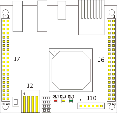
In order to do the very first experiment with the FOX I/O lines we can use the setbits command and the RED LED DL1 mounted on the FOX Board. The state of this led depends by the value of the Port A bit 3 (PA3):PA3=0 DL1 on PA3=1 DL1 offUsing the setbits command it is possible to set or reset any output line with the following syntax:
setbits -p port -b bit -s statewhere:
- port is the port to use, valid values are a,b or g
- bit is the bit number to change
- state is the state to set up
# killall statusled
# statusled off
Now turn on the RED led typing:
# setbits -p a -b 3 -s 0and turn off it typing:
# setbits -p a -b 3 -s 1
Connect a LED on an output line
|
Let's try to connect an external LED on the extension socket J7. As shown figure, we are using for example, the output line OG25 (pin J7.13). The FOX output line cannot drive directly a LED so you have to use a serial resistor to lower the voltage to the LED and limit the current flow through it. Use only low power leds (2mA).
In this case to switch on and off the led just type: # setbits -p g -b 25 -s 1 # setbits -p g -b 25 -s 0In this case we use value 1 to switch the LED on and 0 to switch it off. If you don't know how to manage a led or a resistor please take a look at this site: http://www.theledlight.com/ledcircuits.html Read an input lineTo read all the input lines we can use the command readbits typing:# readbits 111XXX1X XX01XXX1 XXXXXXX11111111111111111XX11111XThe values shown represents the current state of all the input lines as shown in the following map: 111XXX1X XX01XXX1 XXXXXXX11111111111111111XX11111X 7......0 7......0 31.............................0 -PORT A- -PORT B- -PORT G-------------------------The bits with an X are the output lines. The switch SW1 on the FOX Board is connected to the bit 1 of the Porta A. When the switch is pressed this bit goes to electrical and logic value 0. # readbits 111XXX0X XX01XXX1 XXXXXXX11111111111111111XX11111XIt is possible to use readbits to read just one line: readbits -p port -b bitFor example: # readbits -p a -b 1 0 |
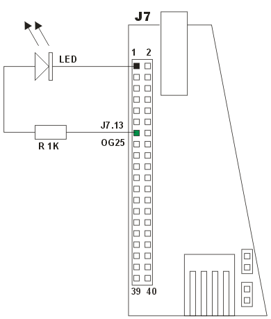
Example of schematic to connect an external LED |
Connect an external switch |
|
|
On figure is shown a simple schematic to connect an external switch to the extension socket J7. When the external switch is released, the pull-up resistor sets the input line to 3.3 volt that's read by programs as logic level 1. When the external switch is pressed the input line go down to GND (ground) that's read by programs as logic level 0.
The readbits result when the switch is released is: # readbits 111XXX1X XX01XXX1 XXXXXXX11111111111111111XX11111XThe readbits result when the switch is pressed is: # readbits 111XXX1X XX01XXX1 XXXXXXX11111111011111111XX11111X |
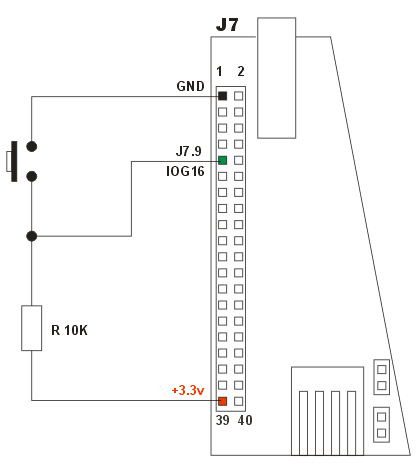
Example of schematic to connect an external switch |
