FVBE - EventCounter1by Roberto AsquiniMake a hardware 16 bit event counter with alarm output on reaching a preset value. |
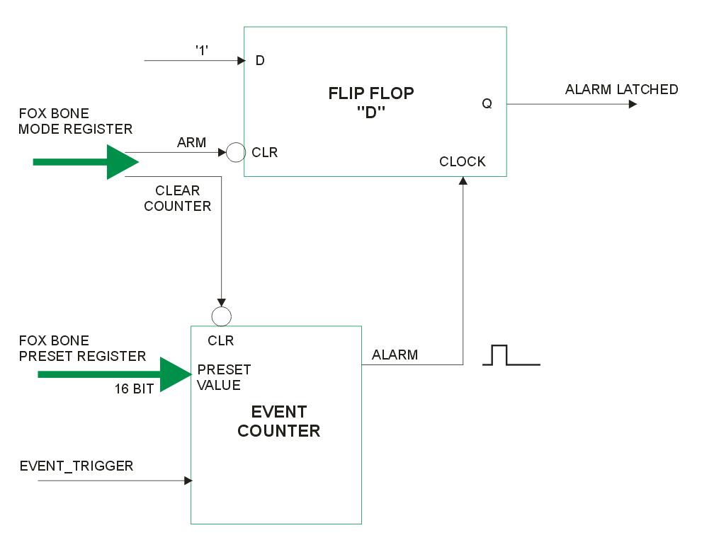
Block diagram of the EventCounter1 function
This example presents a 16 bit programmable event counter that has also a memory alarm. It can be used to wait a programmable number of pulses/events occurring on the EVENT_TRIGGER line before setting up a very fast permanent signal of alarm on the ALARM_OCCURRED port signal. The example will show how to program it to light up an external LED when the programmed number of pulses is reached. This example uses, as usual, a Fox Board coupled with a Fox VHDL board.
Signature release register values for this example (How To access FoxBone registers from the FOX BOARD):
	0x0004=0x0070
	0x0005=0x2323
	0x0006=0x0002
	0x0007=0x0001
The example is composed of two VHDL files. The first file: EventCounterWithAlarm1.vhd that realizes the inner part of the example with the logic needed to implement the Event Counter, with also the filter for the race conditions of the counter.
@idea Race conditions are treated in this article: Understanding Race Conditions in Logic Programming
The other file FoxBone_EventCounter1.vhd is a wrapper file that permits the working of the event counter under the FoxBone specifications. So we will be able to access the Event Counter functionalities through some foxbone registers from the Fox Board software side. This file adds also a D flip flop to be used as a permanent alarm condition flag.
In particular, these are the relevant FoxBone registers for this application and their meaning:
- -- 0x0004: readable register returning the FoxBone release (presently 0x0070 or 0.7.0)
- -- 0x0005: first hardware application word returning 0x2323 (FoxBoneExamples)
- -- 0x0006: second hardware application word returning 0x0002 (stands for example 2)
- -- 0x0007: third hardware application word returning 0x0001 (release 1 of example 1).
Those above registers are present in every foxbone implementation to help the application software to recognize the correct program of the FPGA inside the Fox VHDL board to avoid uncorrect driving of the hardware peripherals inside the FPGA.
- -- 0x0040: Mode Control Read/Write Register for the Event Counter that can be written with the desired value.
-- bit 0 = 1 will arm the event counter
-- bit 0 = 0 will clear the event counter and reset the Alarm line to zero.
-- bit 1 = 1 will arm the Alarm latch to store the alarm condition when occurring.
-- bit 1 = 0 will reset the Alarm latch
-- bits 2-15 unused. - -- 0x0041: Preset Register that can be written with the prefixed value
-- It can be read back from the FoxBone interface. - -- 0x0042: Counter of occurred events register: It can be read back from the FoxBone interface.
- -- 0x0043: Alarm register: It can be read back from the FoxBone interface.
-- bit 0: alarm condition. It will be set when the EventCounter register will reach
-- the preset register value.
-- bit 1: it is the filtered version of the alarm condition
-- with no races caused by the upcounter.
-- bit 2: it is the latched version of the filtered alarm condition
-- bit 3-15 unused.
-- Bits 0,1, and 2 of 0x0043 will go also externally to alarm the field.
How it works
The Event Counter function is realized using the code of two other examples: UpCounter1 and Equal Comparator 16 bit.
There are three processes working together. The first, upcounter, is a 16 bit counter that is incremented on rising fronts of the external EVENT_TRIGGER signal.
The second process is a 16 bit Comparator that recognizes when the upcounter reaches the PRESET_VALUE programmed, rising the EQUAL signal.
The third process is a modified version of the Comparator, called filteredComparator. It makes the comparison between the PRESET_VALUE-1 and the counter at every occurrence of falling edges of the EVENT_TRIGGER so it is not affected by race conditions of the upcounter. When the counter has reached the PRESET_VALUE-1 the process sets high the variable (armed). The new output signal is the AND operation between this armed signal and the EVENT_TRIGGER so the final result will be a high pulse only when it will occr the n-th pulse on the EVENT_TRIGGER line, avoiding all the races since the comparison is made on the opposite front of the EVENT_TRIGGER signal with respect of the increment (with races) of the upcounter.
How to test it immediately
To try immediately the EventCounter function you can download and save on your PC the FPGA programming file: FoxBone_EventCounter1.stp.
Then follow the programming instructions on: Flashing the FOX VHDL FPGA with a new hardware image to program the Fox-VHDL FPGA.
To program the FPGA and test it you should have the Fox programmed with a fimage capable to drive the Fox-VHDL board.
Hardware test bench
Now we are ready to test our Fox-VHDL Example EventCounter1.
Connect together pins JP3-5 (output of Fox PortB7) and JP3-36 (input of the EVENT_TRIGGER for the Event Counter).
Connect also a LED or an oscilloscope to the ALARM_OCCURRED output (JP3-8). The LED will lit when (after the reset of the event counter) the n-th rising edge will be sensed on the EVENT_TRIGGER input. The value of "n" has to be written in the foxbone register 0x0041 as explained in the following.

Schematic of the hardware connection
Download and save on the Fox Board directory /mnt/flash the following program to be able to generate events for the Fox VHDL Event Counter on the Fox Board PortB7 output pin that is located also on FOXVHDL Board JP3-5: PB7pulses. Then make it executable with the command:
cd /mnt/flash
chmod +x PB7pulses
Now you are able to generate a number of pulses on the output port PB7 of the Fox Board. You can also insert as parameters the uptime and downtime for the pulses. Invoking it without parameters it is possible to see an example of use:
# cd /mnt/flash
# ./PB7pulses

PB7pulses usage: PB7pulses numpulses timehigh timelow
 numpulses has to be entered in decimal. times are in us
 Press ENTER anytime to exit.
Typical usage:
PB7pulses 5   (generate 5 pulses on port PB7 (FoxVHDL JP3-5)
#
@idea To have a look at the inner workings of this simple program download its source: PB7pulses.c
Now to start the test we have to reset the event counter and then arm it again writing on the 0x0040 foxbone register so it can go off in alarm when the preset count written in the foxbone register 0x0041 is reached. The alarm conditions are visible, other than on the JP3 pins also reading the foxbone register 0x0042.
So to operate correctly the Event Counter1 function do the following from /mnt/flash where you saved before the PB7pulses program:
#
# foxbone o 41 0003
FoxBone output data 0x   3 on addr 0x0041
# foxbone o 40 0
FoxBone output data 0x   0 on addr 0x0040
# foxbone o 40 3
FoxBone output data 0x   3 on addr 0x0040
# ./PB7pulses 7 1 1
7 1 1
#
The following oscilloscope display shows the result on the FOXVHDL JP3 pins.
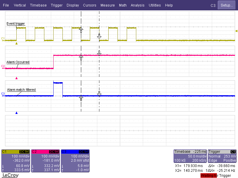
Oscilloscope display of the Event Counter test for count = 3
In the following display instead we show the third rising front of the Event Trigger input (connected by a wire to the port PB7) zoomed in time to show the delay between the input trigger and the output of the hardware function. It is possible to see that the circuit programmed inside the FPGA is capable to react to the n-th pulse within 12 nsec.
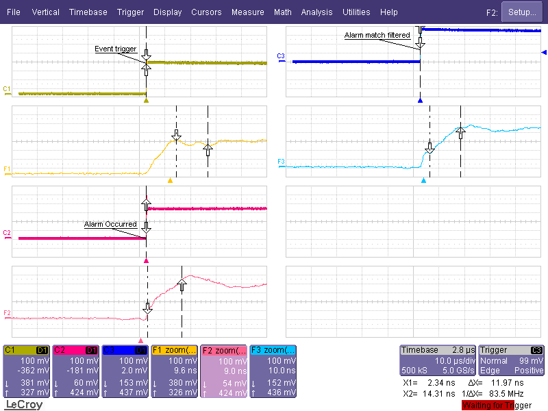
Oscilloscope zoomed display during the third rising front of Event Trigger in the Event Counter test
Test the Event Counter1 with the event application
Inside the FOX image able to program and drive the FOX VHDL board, there is also installed a kernel driver specifically designed to operate with the foxbone registers of the foxbone Event Counter1 application. In other articles we will explain how to build a Linux kernel driver for a foxbone peripheral so to exploit the max performances from it. Here we would like to show a simple way to interact with the Event Counter1 function with a simple command line tool that is also inside the FOX Board image fimage_300_v100.zip.the event tool
# event
event usage: event command value
valid commands:
s = set alarm  (value = number off events until alarm is triggered);
c = get the current event count ;
a = find out if an alarm has occured
r = reset the event counter

Typical usages:
event s 5 (alarm will trigger after 5 events)
event c   (clear pin 2)
event a   (check if alarm has occured)
event r   (reset alarm and counter)
#
As you can see above, invoking event from a console or telnet session of the FOX, you can have the possible options to use the tool. It is very simple to use this tool also inside a script. To be able to generate the same output as above from the Event Counter1 function, operate as follows:
# event r
# event s 3
# ./PB7pulses 7 1 1
7 1 1
#
Here is reported the sourcecode of the event tool to show the way to write a program that uses the custom kernel driver of the Event Counter1 foxbone function: event.c
@idea To continuously monitor the status of up to four FoxBone registers from a console session you can find useful this little utility: A FoxBone Register Monitor Utility
Libero Designer Layout Report
This is the Status Report for the Event Counter1 through FoxBone that can be obtained in the Libero Designer session under the Menu: Tools - Reports - Status Report after the Layout compiling phase of the project.
Compile report:
===============

    CORE                     Used:    306  Total:   6144   (4.98%)
    IO (W/ clocks)           Used:     24  Total:    157   (15.29%)
    Differential IO          Used:      0  Total:     38   (0.00%)
    GLOBAL (Chip+Quadrant)   Used:      0  Total:     18   (0.00%)
    PLL                      Used:      0  Total:      1   (0.00%)
    RAM/FIFO                 Used:      0  Total:      8   (0.00%)
    FlashROM                 Used:      0  Total:      1   (0.00%)
As you can see The logic for the Event Counter function and relative FoxBone registers are
occupying only 4,98% of the FPGA logic space.
Download the whole project to install and recompile it in your PC
Here is the link to download a zipped copy of the entire FoxBone_EventCounter1.zip Libero 7.1 project. Please refer to the Libero projects download and installation page to be able to recompile the project, to simulate it and generate the programming .stp file to program the FOXVHDL FPGA.The only very important file to consider other than the .vhd files of the project, is the physical constraint file that maps the port signals of the VHDL project to the physical pins of the FPGA. It is easy to see that the maximum effort has to be applied to avoid mistakes on this file, since a wrong map of an output of the FOXVHDL board to an output of the Fox Board can result in a misfunctioning or to a damage for the internal output stages of the Fox-Board or the FOXVHDL board. We provided current limitation resistors on all the lines to avoid this but we cannot guarantee against a very wrong mapping of several outputs together, so be very careful when mapping the physical pins of your application.
You can find here the FoxBone_EventCounter1.pdc constraint file that is also, when installed the project in your PC, under the projects FoxBone_EventCounter1\constraint directory. You can see in the .pdc file, for every function pin, other than the settings for its electrical behaviour, the mapping to the correct physical FPGA pin. You can face this information with the schematic file of the FOXVHDL board to see that they couple exactly for the interfacing with the Fox Board J6 and J7 connectors. The output function signals have instead been routed to the FPGA pins that are connected to the external connector JP3 of the FOXVHDL Board.
The physical constraint file is generated automatically as an export file inside the Designer session of your project. It is possible to assign the mapping of the pins in the IO Attribute Editor inside the Designer application of the Libero suite.
