FVBE - Frequency Doublerby Roberto AsquiniMake a Synchronous External Signal Frequency Doubler |
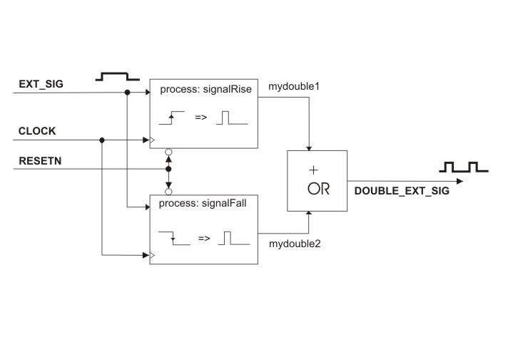
Block diagram of the Synchronous Signal Doubler function
This example presents a VHDL code and its simulation that synchronizes an external signal with an internal clock, delaying it by one period of the internal clock and doubling the external frequency generating a high pulse on the output signal DOUBLE_EXT_SIG for every rising and falling fronts of the external signal EXT_SIG. The example will show how to use state machines inside two processes to achieve the resulting goal to double the frequency in input and delay it by a value comprises between one and two internal clock pulses synchronizing the external signal to the internal clock. This example forms the base concept used to realize double data rste transmissions on the Fox Bone interface rel. 1.0.
The example is composed of the single VHDL file: SynchronousSignalDoubler.vhd
How it works
To be able to react to both fronts of the external signal EXT_SIG we split the functionalities between two separate processes: processRise and processFall. The first takes care of the rising front of EXT_SIG. The other tales care of the falling edge. To be able to delay and generate complete pulses starting from a single signal front, we employed two state machines with three possible states each. Every process starts execution only at rising fronts of the internal CLOCK port signal. Starting from state0 at startup, the first process will wait for the occurrence of the logic state '1' on the EXT_SIG, passing then in state1. At the next rising front of the internalCLOCK the process will resume execution. Now being in state1 it will raise its output pulse mydouble1 and passes in state2 the state machine. At the next clock rising fronts the process will stay in state2 till EXT_SIG will remain in logic state '1' to avoid that the state machine will regenarate other pulses. When EXT_SIG will return to '0' the state machine is reset to state0 and the process is so rearmed to process another EXT_SIG rising front.
The second process is similar but acting on falling fronts of the EXT_SIG signal. It will output its pulses on the mydouble2 signal.
The logic OR of the two signals: mydouble1 and mydouble2 will result in the DOUBLE_EXT_SIG output port signal, the main output of this function that doubles the frequency of EXT_SIG delaying its rising fronts with respect to the EXT_SIG fronts.
Simulation of the Synchronous Signal Doubler
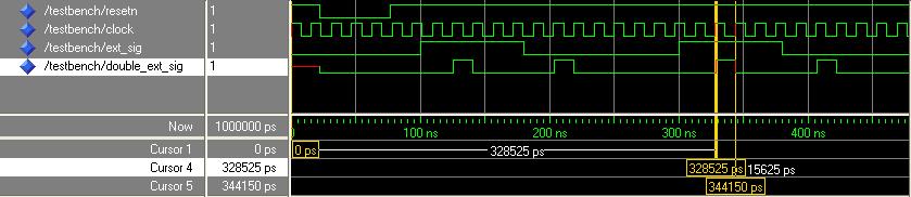
Simulation of the Synchronous Signal Doubler function
@idea Remember that VHDL is not case sensitive! So, even if we declared the port signals in upper case, the simulator shows anyway all names in lower case.
It is possible to see in the simulation diagram that at startup, when the resetn signal is low, the main output double_ext_sig is initialized at '0'.
The ext_sig then goes high. It is followed by a pulse (generated by the first process) on double_ext_sig at the second coming rising front of clock. The pulse is wide exactly one clock period. We used for the simulation a clock of 64 MHz, that corresponds to the oscillator frequency of the FOX VHDL board. You can see in the second part of the diagram the measure of the length of the double_ext_sig pulse that is precisely 1/64MHz = 15.625 nsec.
When a falling edge of ext_sig occurs, double_ext_sig generates another pulse high (generated from the second process), delayed from one to two clock periods and with length again of one clock period.
The limitation of theis signal doubler is the maximum frequency on ext_sig that has to be les than one quarter of the clock frequency. More precisely every semiperiod of ext_sig cannot be shorter than two complete clock periods or the pulses on double_ext_sig will not be generated or will be misplaced (they can be placed outside the corrspondent semiperiod of ext_sig. If we use a 50% duty cycle waveform for ext_sig and the clock frequency is 64 MHz, the maximum frequency for ext_sig to have this code working well is 16 MHz. If we would not need the delay we could achieve a higher max input frequency. It is possible also to generate shorter pulses or shift higher the clock frequency with the PLL inside the FPGA of the FOX VHDL board to work at higher frequencies. For the purposes of the FoxBone double data rate transmission interface this setup has been safe and sufficient to get the FoxBone go faster and to reduce the number of instructions on the Fox side to write on the FoxBone registers since the possibility to delay the write signal permits to the Fox software to put at the same time the data on FoxBone lines and the write signal at '1' since the FPGA will acquire the data lines with one clock period of delay. Since the min period of the write operations is around 80 nsecs (corresponding to a max frequency of 12.5 Mhz) this code is well designed to cope with the frequency constraint of the FoxBone double data rate interface of FoxBone specifications release 1.0.
In Depth: SynchronousSignalDoubler.vhd description
The VHDL code SynchronousSignalDoubler.vhd has been used as a part of another project for doubling the data rate transmission for the FoxBone specifications release 1.0, however in this example is not presented a full FoxBone peripheral but only the necessary parts of code to be able to simulate it as prove of concept and as an example of the implementation of state machines in VHDL.
The entity declaration shows the necessary port signals to feed the module: the CLOCK, the active low RESETN to reset all the internal logic states, the EXT_SIG that is the external signal that will be synchronized, delayed and frequency doubled on the port output signal DOUBLE_EXT_SIG:
entity SynchronousSignalDoubler is
 port (
    RESETN: in std_logic;  -- reset signal active low
    CLOCK: in std_logic;   -- internal board clock
    EXT_SIG: in std_logic; -- external signal to be doubled
    DOUBLE_EXT_SIG: out std_logic -- output of the doubled and synchronized clock signal.
    );
end SynchronousSignalDoubler;
Then at the beginning of the architecture declaration we defined a custom enumerative type to be used by the state machines as state values:
 type mystates is (state0, state1, state2); -- declaration of the internal states of the
                                            -- two state machines needed for this example

 signal sigstate1,sigstate2 : mystates; -- instantiation of two internal state memories that can
                                        -- assume values of the custom type mystates
 signal enablestates: std_logic;        -- we need another initial state to avoid unwanted pulses
                                        -- at startup.
 signal mydouble1: std_logic; -- every one of these two signals will generate a pulse for every
                              -- different front of the external EXT_SIG port signal.
 signal mydouble2: std_logic;
other three signals are declared: enablestates is used to block the second process at startup till the first has executed the first run, to avoid the generation of a wrong output pulse just after the RESETN active phase. mydouble1 and mydouble2 are the two outputs from each of the two processes that will be combined to deliver the main function output.
The first process: processRise
In the first process processRise, then, there is the startup part that, when RESETN is '0' will reset the first state machine value sigstate1, it resets also the enablestates and the output of this process: mydouble1.
    -- first process: we process here the rising fronts of the EXT_SIG signal.
    signalRise: process (CLOCK, EXT_SIG, RESETN)
    begin
      if RESETN = '0' then
        -- at startup reset states and output
        sigstate1 <= state0;
        enablestates <='0';
        mydouble1 <= '0';
      elsif (CLOCK'event and CLOCK = '1' ) then
If it is not the reset phase, the process will act only at rising fronts of the
CLOCK signal. So, during normal work, at every rising front of CLOCK,
the first process will execute the following code:
        case sigstate1 is
          when state0 =>
            if (EXT_SIG = '1') then -- when EXT_SIG goes high wait one internal clock
                                    -- before raising the pulse. Pass to state 1.
              sigstate1 <= state1;
              enablestates <= '1'; -- so it enables the next falling front
                                   -- of EXT_SIG to generate a pulse.
            else
              sigstate1 <= state0;
            end if;
          when state1 =>
            sigstate1 <= state2;  -- now raise the pulse and pass to state 2
            mydouble1 <= '1';
          when state2 =>
            mydouble1 <= '0';
            if (EXT_SIG = '1') then
              sigstate1 <= state2;  -- stay here up to the falling edge of EXT_SIG
                                    -- avoiding multiple pulses if EXT_SIG is long enough.
            else
	          sigstate1 <= state0;  -- EXT-SIG has fall. Rearm the waiting of the rising front
            end if;
        end case;
      end if;
    end process signalRise;
The action taken by the first process at every rising front of the CLOCK signal will be determined by the value of the state variable sigstate1. It can assume only three values: state0, state1, state2.
state0 is the state where the state machine waits for the occurrence of a rising front of the EXT_SIG. Infact when sigstate1 is equal to state0 the process tests if the logic state of EXT_SIG is '1' and in case, it passes to state1. It also set the enablestates signal to '1'. If EXT_SIG is '0' instead the state machine remains in state0.
state1 is the state when the EXT_SIG has rised, so at the nect rising CLOCK front the process sets high its output mydouble1 and passes to state state2. Having the state machine wait for one state transition before setting hig its output will delay mydouble1 of at least one period of the internalCLOCK with respect to EXT_SIG.
In the state2 state the occurrence of a rising CLOCK front will unconditionally set low the output mydouble1 which has stayed up for precisely one CLOCK period only. The state machine now will wait the falling edge of EXT_SIG to return to state0 and rearm itself to wait other rising fronts of EXT_SIG.
The second process: processFall
The second process processFall acts like the first process but waiting falling edges of EXT_SIG and generating one period of CLOCK long pulses on its output mydouble2.
The only difference the second process has with respect to the first one is that the process is blocked at startup from the enablestates signal that is set to '0':
      if RESETN = '0' then
        -- at startup reset states and output
        sigstate2 <= state0;
        mydouble2 <= '0';
      elsif (CLOCK'event and CLOCK = '1' and enablestates = '1') then
        -- it executes only after the first rising front of EXT_SIG
        ....
The last statement will join mydouble1 and mydouble2 with a logic OR operation so to have on the main function output port signal: DOUBLE_EXT_SIG the two pulses generated by the two processes in correspondence to both rising and falling fronts of EXT_SIG:
    -- this last statement will join the two separate generated pulses,
    -- one for each front of the EXT_SIG port signal, exporting the OR combination of them
    -- as a single port output signal.
    DOUBLE_EXT_SIG <= mydouble1 or mydouble2;

end Behavioral;