PLEASE NOTE: This article is obsolete or related to a discontinued product.
FOXPxx prototyping boards
The FOXPxxx prototyping boards are specifically designed for developers who need to make hardware experiments with their FOX Boards
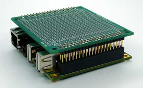
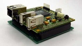
The FOXPxxx prototyping boards have the same FOX Board size and can be connected to the FOX Board by its J6 and J7 extension sockets in two ways as shown below:
|
Top mounting like and add-on boardThis solution is compatible with the TUX Case and the FOX Case.It needs a pair of female sockets (item STRIPF2X206MM) welded on the top side of the FOX Board and a pair of male headers (item STRIPM2X2012MM) welded on the bottom side of the protoboard. |
|
Bottom mounting like a carrier boardThis solution is not compatible with the TUX Case and the FOX Case and is not so comfortable to have access to the components mounted on the prototyping board.It needs a pair of male headers (item STRIPM2X206MM) welded on the bottom side of the FOX Board and a pair of female sockets (item STRIPF2X206MM) welded on the top side of the prototyping board. |
FOXP254 - Prototyping board step 2.54mm (100 mils)
|
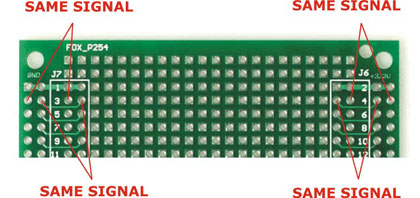
The FOXP254 prototype board has a double side soldering area of 22x24=528 metallized holes in step 2.54 mm (100 mils)
and is useful to do experiments with dual in-line ICs (@wikipedia='Dual_in-line_package') and through hole
(@wikipedia='Through-hole_technology') discrete components.
J6 and J7 signals are replicated inside the prototyping area to easy signal probing with tester and oscilloscope.
|
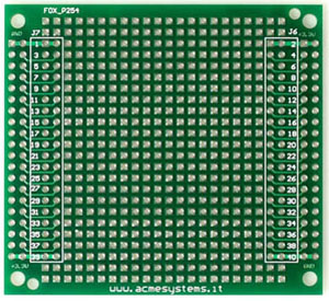
FOXP254 Prototyping board step 2.54mm (100 mils) Zoom |
FOXPSO - Prototyping board step 1.27mm (50 mils) for SMD components
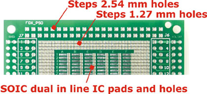
The FOXPSO prototype board has a double side soldering area of:
Like the FOXP254 prototyping board, also the FOXPSO has J6/J7 signals replicated inside the
prototyping area.
|
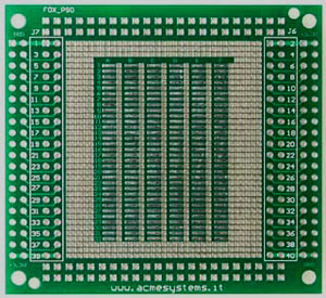
FOXP_254 Prototyping board step 1.27mm (50 mils) Zoom |
