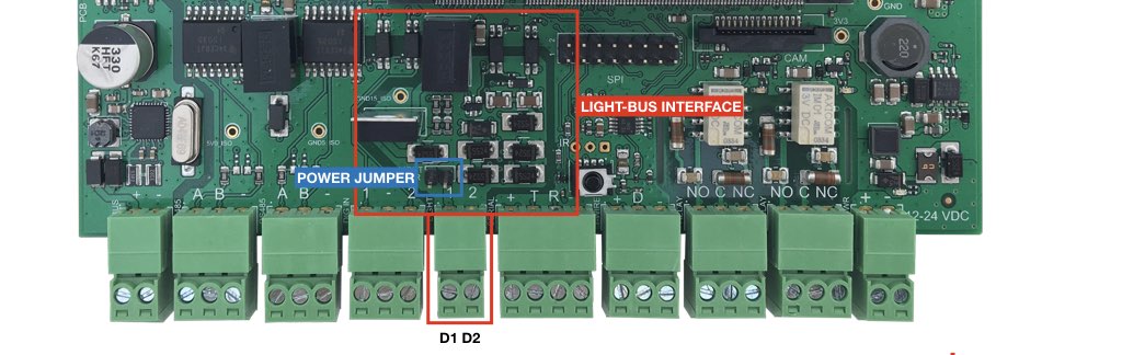
DALI bus interface
Warning: CM3-Home is not a certified DALI controller !
An open hardware is implemented on it so we can't warranty the fully functionality with any DALI devices
Features
- Signals available on two screw terminals
- Bus opto-isolated from the CPU side
- Power supply provided on the bus for up to 16 devices without need an external power supply
- Bus managed in bit banging mode
- Available only on CM3-HOME-F
The DALI protocol
The physical interface consists of 2 wires, DALI Power and DALI Data. The DALI system consists of one DALI Control module with up to 63 DALI devices.
- DALI Power line provides the power only for the communication protocol of a maximum 22.5V and limits the current for the system to 250mA.
- The DALI Data line provides the half duplex communication at a data rate of 1200 bits/second using a bi-phase (Manchester) decoding.
Bi-phase decoding is accomplished with the following:
- a logical zero consist of sending a physical low signal for 416 µs immediately followed with a physical high signal for 416 µs.
- a logical one consists of sending firstly a physical high signal for 416 µs followed by a physical low signal.
A physical high signal on the DALI Data line is a voltage level between +9.5V and +22.5V. A physical low signal on the DALI Data line is a voltage level between -6.5V and +6.5V.
The DALI digital layer consists of 2 frames, a forward frame and a backward frame.
- A forward frame is a frame sent from a DALI controller to a DALI ballast. It is constructed by a START bit (always logical 1), followed by 1byte Address,1byte Command and two STOP bits (a high level with no transitions).
- A DALI ballast communicates back to the DALI control using only a 1byte backward frame consisting of a START bit,1byte,2 STOP bits.
The DALI protocol allows a master controller options to address all ballasts by either broadcast to all, Groups of ballasts, and individual addressing.
The most commonly used direct commands allow the controller to modify lighting brightness, scene settings for groups, fading capability and varying rates. Also including are Query command that request the ballast to send a backward frame with configuration data such as, power levels, scene levels, current address.
Using “extended” Configuration command the DALI controls can modify addresses of each ballast thus eliminating manual configuration of the DALI system.
The “extended” configuration command will follow immediately after a DALI controller sends an INITIALIZE ($A5) command, which informs all other DALI devices on the bus to ignore further commands until a TERMINATE command is observed or 30 s elapses in time.
GPIO line used:
- The GPIO line used for the TX DALI signal is GPIO 31
