Arietta technical documentation
Using the WIFI module on Arietta G25
Arietta has a placement for an IEE802.11 b/g/n, USB 2.0 OEM WiFi adapter.
This chip is fully supported on the latest Kernel Linux versions and can be used to work in Access Point mode.
WiFi module placement
As shown below Arietta has a placement for 6 strip pitch 2mm where it is possible to place a WiFi module. The WiFi module has a 6 pin male strip already soldered on the bottom side. On Arietta it is possible to place a female connector or to weld the WiFi module directly in case you don't need to remove the module.
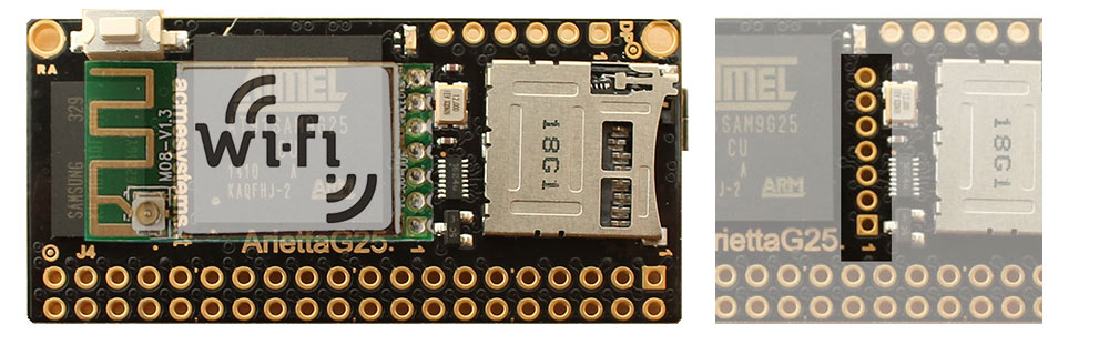
On this pad are presents the USB B host port signals, the power supply line at 3.3 volt DC, and some GPIO used to manage some module function.
| Pin # | Signal | Dir | Description |
|---|---|---|---|
| 7 | WPS | OUT | WSP function. Low level activated. Wired to PC16 |
| 6 | LED | N.C. | WiFi module activity led. Not used |
| 5 | GND | Signal ground GND | |
| 4 | USB B D+ | USB Host B D+ | |
| 3 | USB B D- | USB Host B D- | |
| 2 | VCC 3.3V DC | OUT | Output from the internal regulator from 5 to 3.3 volt |
| 1 | WiFi TXEN | OUT | RF on/off control. Low level activated to off. Wired to PC30 |
When the WiFi module is mounted the USB port B signals on J4.16 (D+) and J4.18 (D-) are not usable
for other purposes.
Setting the WPS and TXEN lines
To activate the WPS mode
echo 80 > /sys/class/gpio/export
echo out > /sys/class/gpio/pioC16/direction
echo 0 > /sys/class/gpio/pioC16/value
To de-activate the WPS mode
echo 1 > /sys/class/gpio/pioC16/value
To turn off the WiFI TX
echo 94 > /sys/class/gpio/export
echo out > /sys/class/gpio/pioC30/direction
echo 0 > /sys/class/gpio/pioC30/value
To turn-on the WiFi TX
echo 1 > /sys/class/gpio/pioC30/value
