How to design the Ethernet circuitry
Introduction
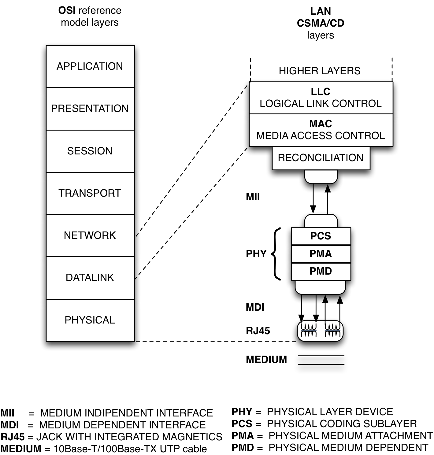
IEEE802.3 standard also defines the protocol (both hardware and software) between the MAC (Media Access Control) and the network medium. In our case the MAC is the hardware peripheral of Microchip SAMA5D27 MCU and the medium is the UTP (cat5 and upper) cable for a 10Base-T or 100Base-TX link.
As shown in the diagram the MAC peripheral allows connection in a medium indipendent way. In order to add to the protocol all the electrical and handshaking controls needed to fit the ethernet requirements on UTP medium, we need another dedicated chip, the PHY. The rules to design the chain from UTP to MAC will be described in a bottom-up fashion, from lower layer up.
Physical
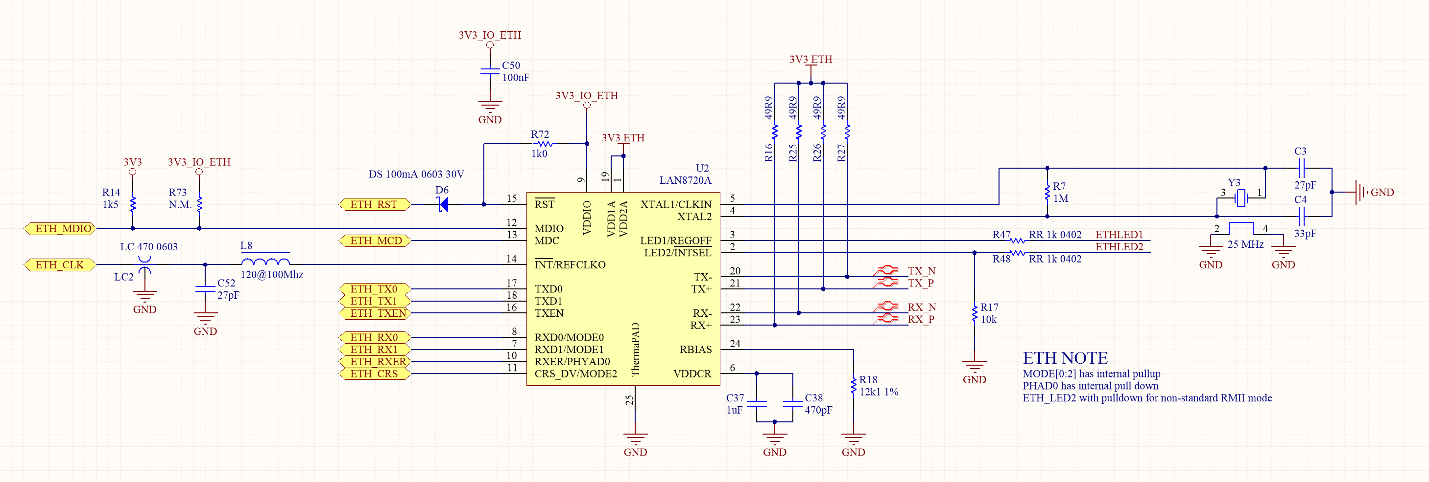
This is the schematic of the physical part of the ethernet connection. Let's describe the role of each component.
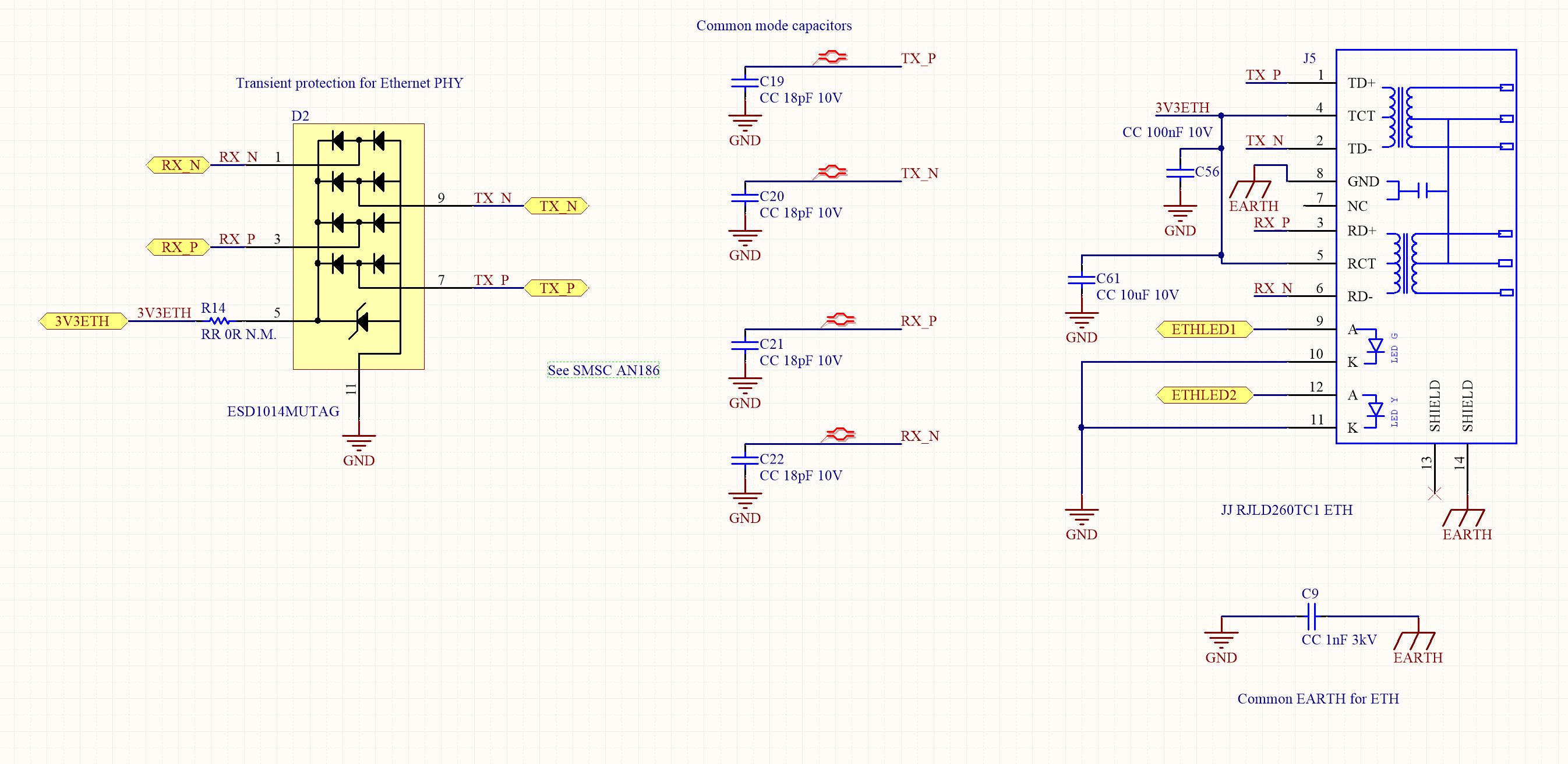 The LAN cable can connect two devices with a distance up to 100m. Those devices can be connected to different power supplies with a ground potential difference of many volts. The cable can also catch some ESD or EMI running togheter with other lines in a service duct. Those dangerous levels must be filtered out before causing damages of any kind. An RJ45 socket with integrated magnetics is strongly recommended because of its galvanic insulation between medium and internal electronics. Furthermore it's designed to match the impedance of the UTP cable and avoid reflections.
RJ45 jacks are available in both SMT or PTH package, examples below.
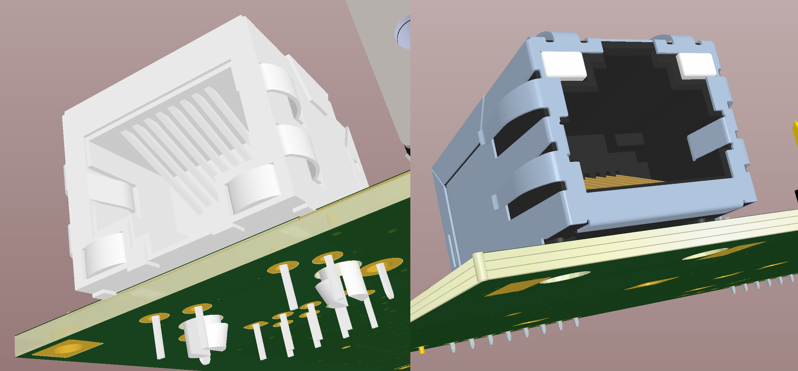
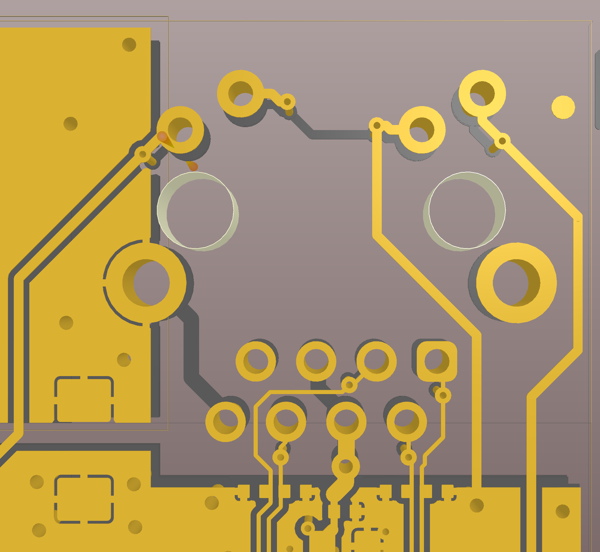
SMT connector is easier to mount with the Pick & Place and it is usually a little bit smaller. PTH is more robust and offers more reliability if it must be plugged often. Below some examples of PCB for SMT and PTH RJ45 connectors. Note the further precautions to avoid ESD damages to sensitive components. The shield of the RJ45 jack is connected on a separated plane, called here EARTH to distinguish it from the general GND plane and insulated from it with at least 1mm gap. The two planes are in contact, from the point of view of the signal, only through a 1nF/3kV capacitor. The 18pF, common mode balancing capacitors must be placed as close as possible to the socket on the edge of the GND plane. Even more ESD protection is given by the ESD1014 ESD Protection Array in parallel to the signal lines and placed close to the EARTH plane.
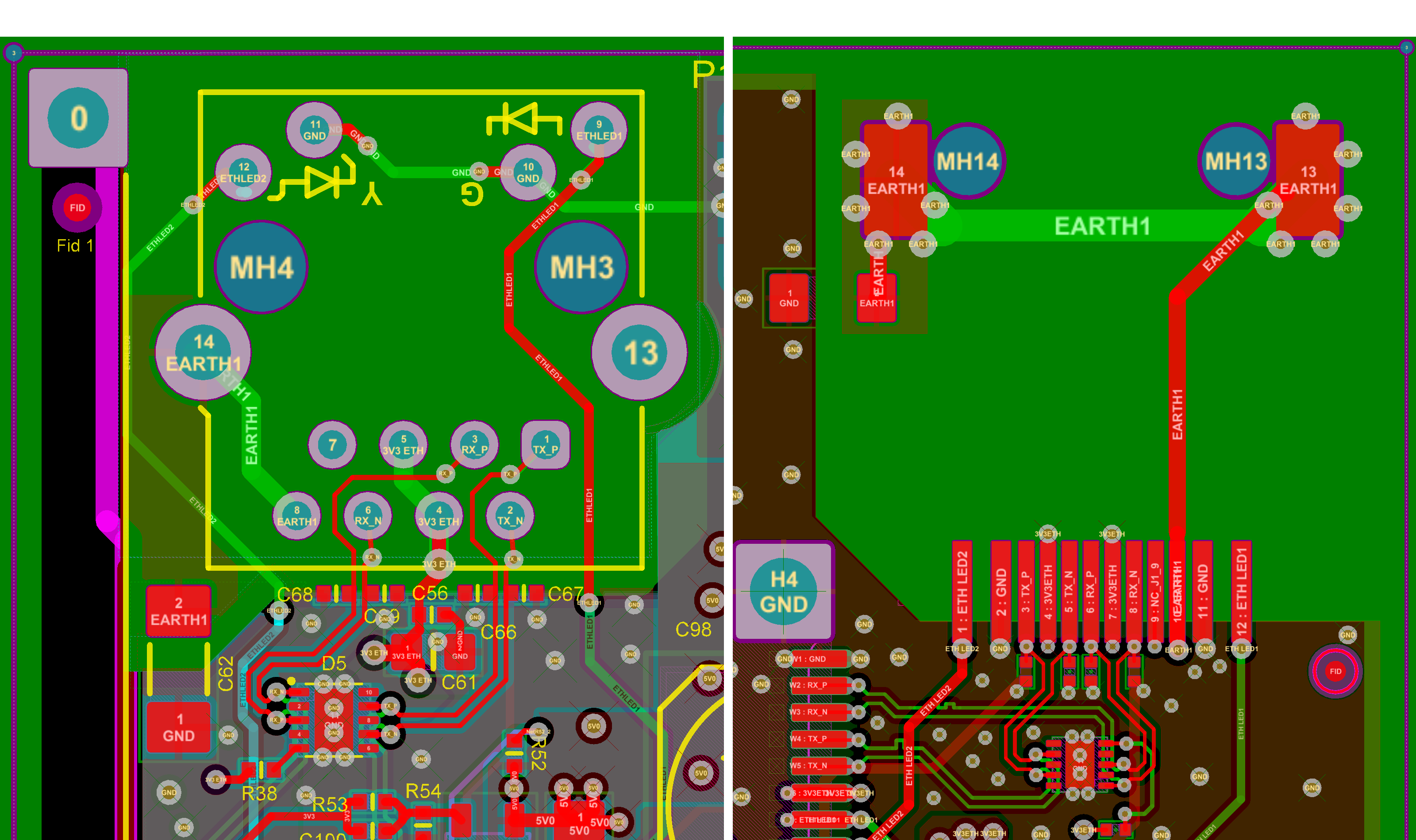
Contrary to the rest of the circuit, no planes at all must be placed under the magnetics, to keep the differential signals paths matched and maintain common mode noise rejection at the best.
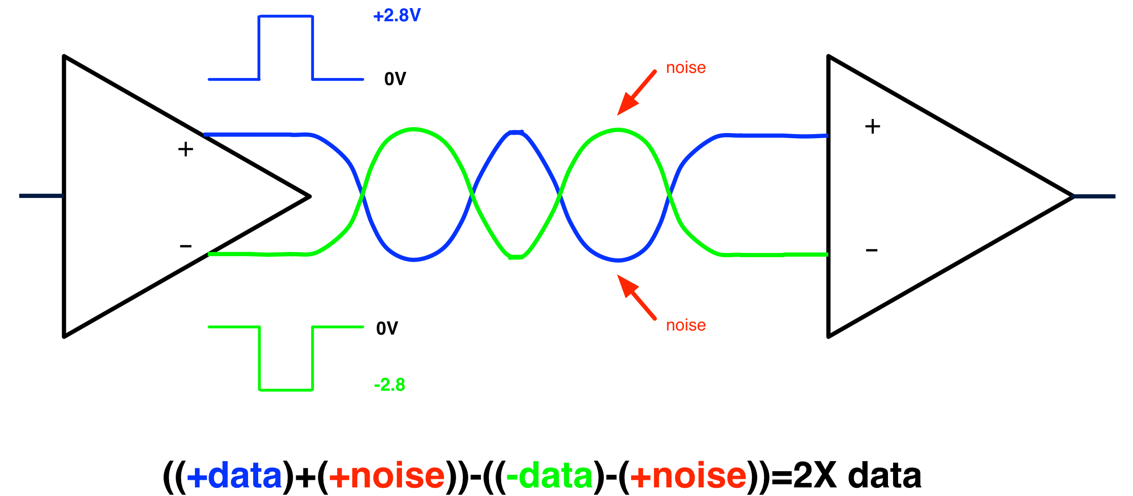
As well-known the 100Base-TX link uses the differential signal transmission mode in order to reject common mode noise induced along the path. Path lenght differences influence phase shift of differential signals reducing consequently S/N ratio. Because it carries a high frequency signal, the UTP cable must have the right impedance to match source and load one.
The lenght matching and controlled impedance requirements must be maintained also on the PCB part of the line, to avoid reflections of the signal and to improve EMC. A set of tools is available in Altium Designer to ease this task.
First of all we must define the correct rules to follow for this kind of routing. The impedance of the tracks depends on the PCB (dielectric and copper thickness at most) and on the width and spacing of the differential lines. A good impedance calculator for this kind of line is TX-line, transmission line calculator.
A suited GND plane must be always present under and around the differential lines, this leads to a minimum of 4 layers PCB. Once the correct parameters has been calculated they must be entered as a rule for that specific net class.
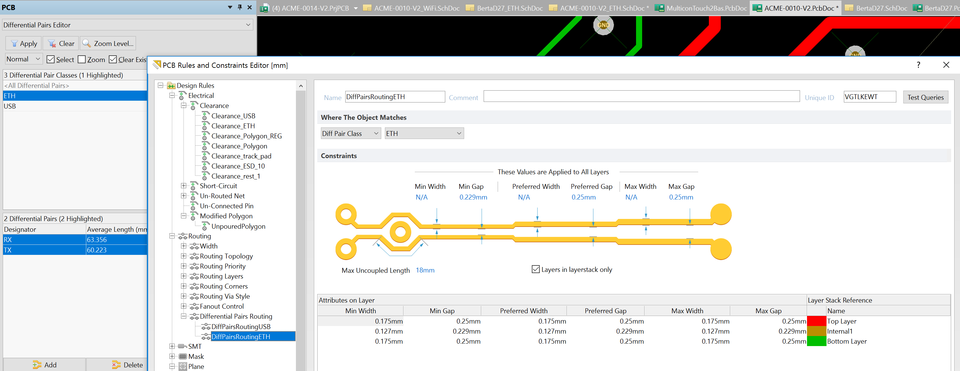
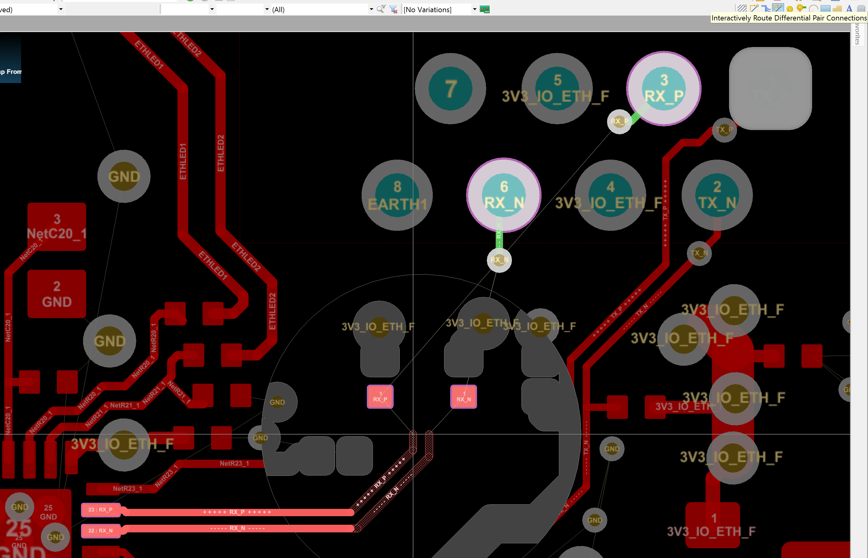
After that, using the Route - Interactive Differential Pair Routing tool, it's easy to route the differential lines with the correct width and spacing.
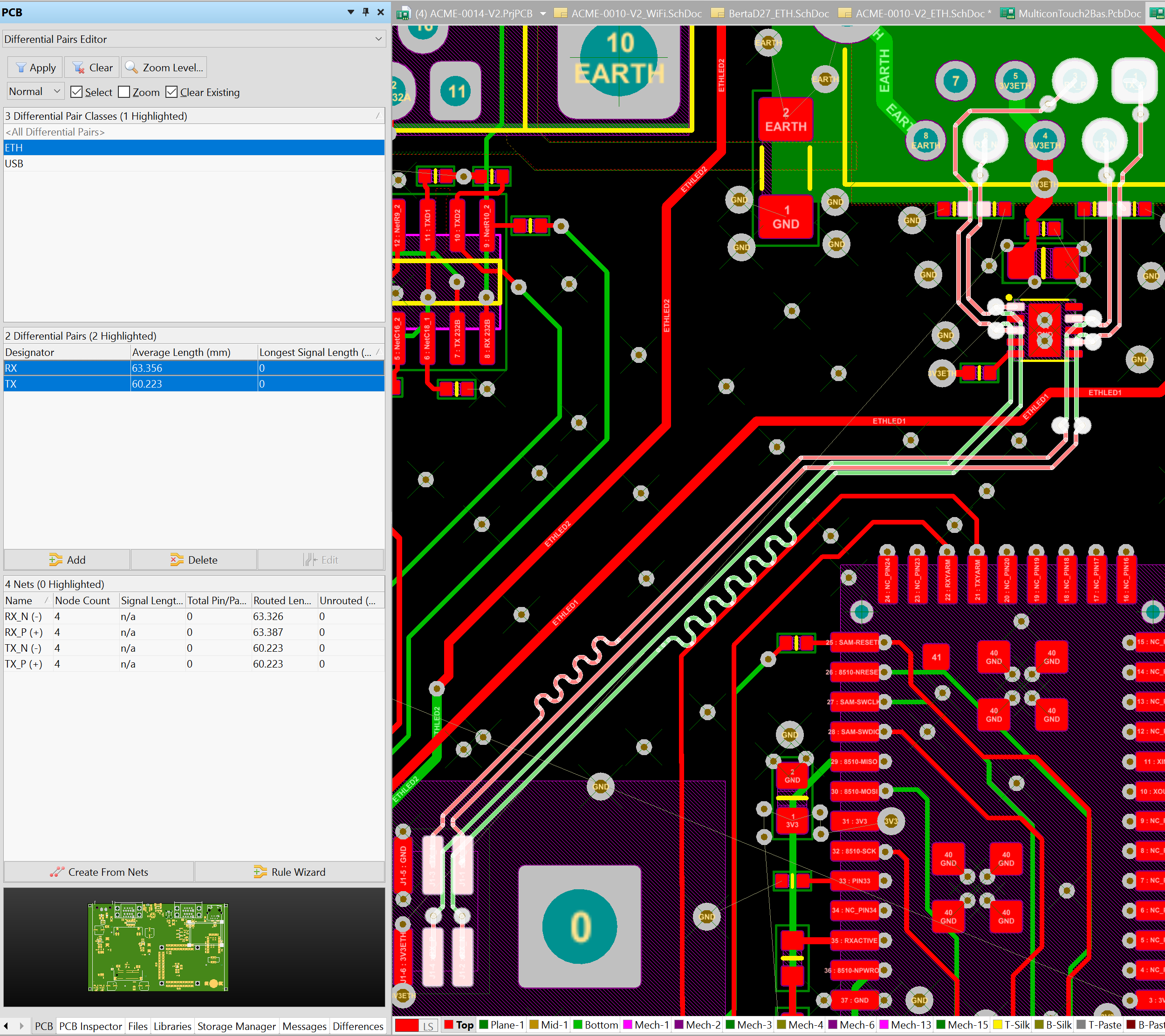
Once routed, the lines must be length matched within some tenths of mm with PCB - Differential Pair Editor tool.
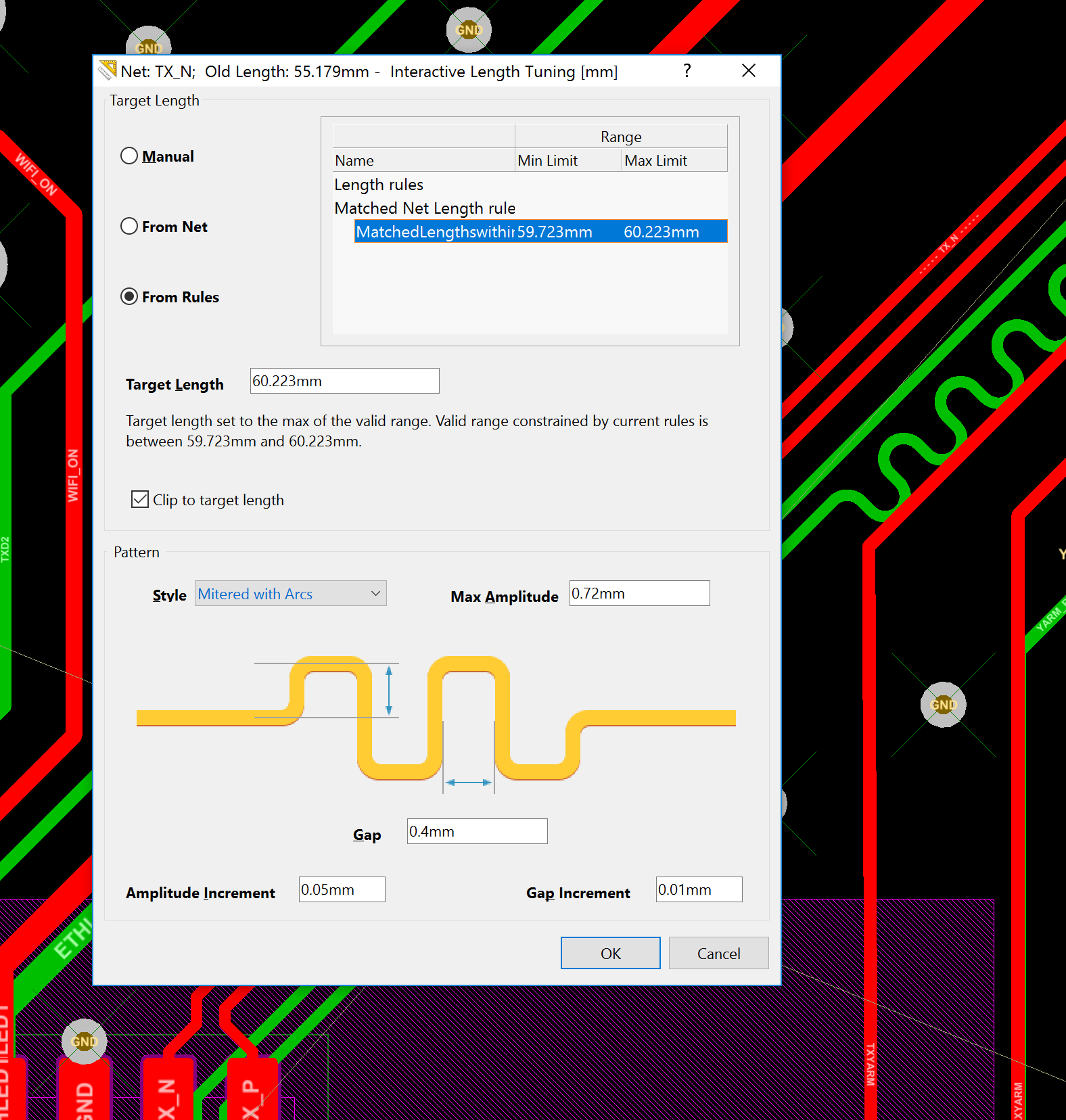
Some possible length differences can be compensated by adding an accordion with interactive length tuning tool.
MDI - PHY
A PHY chip typically used to interface the medium indipendent to the medium dependent part of the circuit is the Microchip LAN8720A 10BASE-T/100BASE-TX transceiver
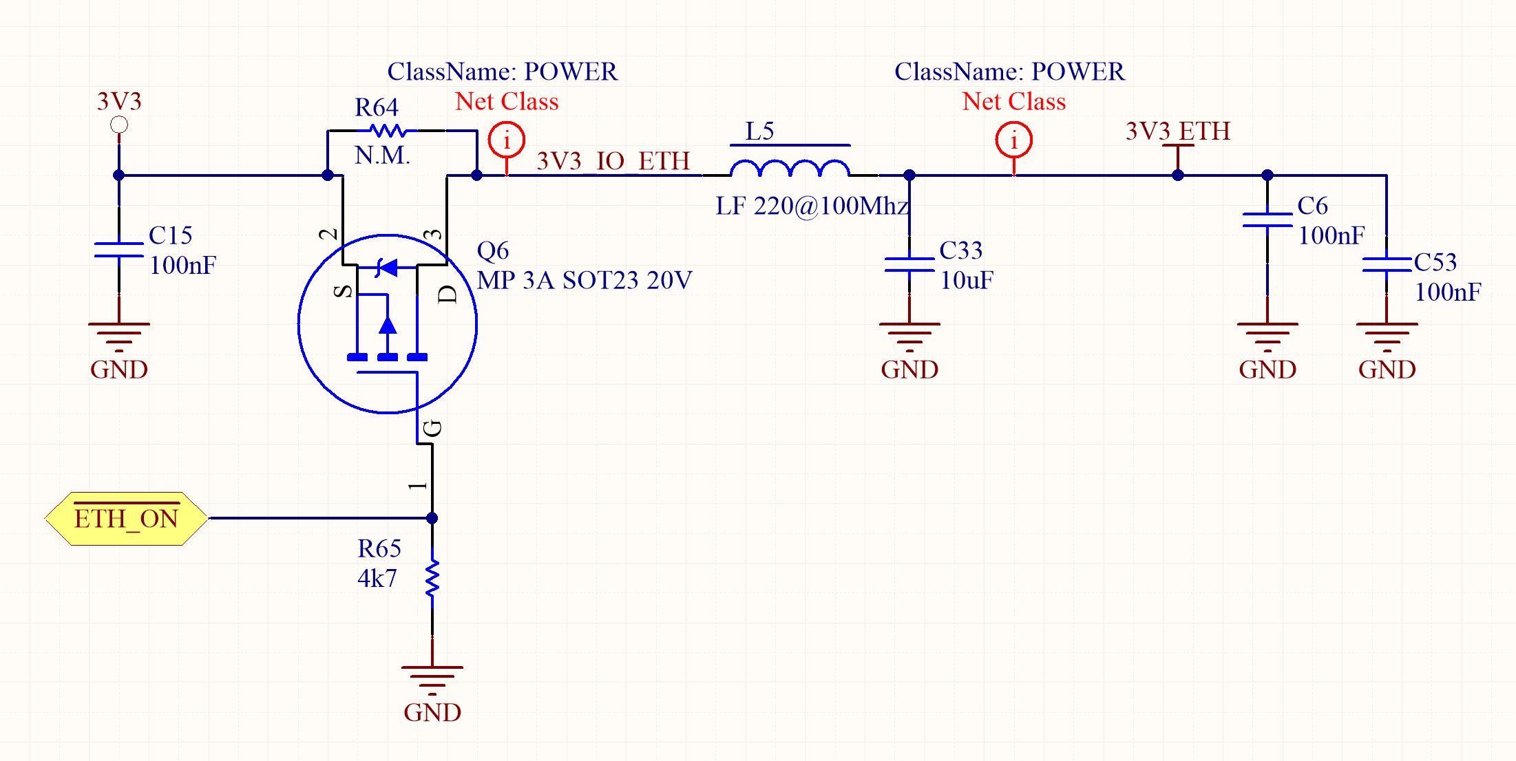
Driving the ethernet line over up to 100m length it requires some power. Once the PHY and the magnetics are switched on they start wasting some hundreds of mA. In order to save energy, when the ethernet is not required, their power can be software controlled in a separated power domain using a mosfet driven by a GPIO of the MCU.
MII/RMII - MAC
The IEEE802.3 standard initially defined the rules for an MII with 4 lines for each signal direction and many control lines. The standard mostly used right now is the Reduced Medium Independent Interface that, doubling the clock and sharing some control lines reduces to a more reasonable number of I/O lines for the MCU MAC peripheral.
Due to a 50MHz communication with sharp edge levels, also the PCB tracks of this part of the circuit must be carefully designed. Even though length matching is not required they must be kept as short as possible, with the clock line possibly longer than the data lines.
RMII signals
| Signal name | Description | Direction |
|---|---|---|
| REF_CLK | Continuous 50 MHz Reference Clock | MAC to PHY |
| TXD0 | Transmit data bit 0 (transmitted first) | MAC to PHY |
| TXD1 | Transmit data bit 1 | MAC to PHY |
| TX_EN | When high, clock data on TXD0 and TXD1 to the transmitter | MAC to PHY |
| RXD0 | Receive data bit 0 (received first) | PHY to MAC |
| RXD1 | Receive data bit 1 | PHY to MAC |
| CRS_DV | Carrier Sense (CRS)/RX_Data Valid(RX_DV) | PHY to MAC |
| RX_ER | Receive Error (optional on switches) | PHY to MAC |
| MDIO | Management data | Bidirectional |
| MDC | Management data clock | MAC to PHY |
