Yarm and alphanumeric LCD 16x2
The Winstar LCD is compatible with the classic Hitachi HD44780 protocol but over an I2C bus instead of a parallel port and its I2C address is 0x3E.
The four push buttons and the LCD backlight are managed through a PCF8574T I2C GPIO expander
The I/O expander I2C address depends on which chip is mounted on the board as listed below:
- PCF8574AT = 0x3F
- PCF8574T = 0x27
In case you don't need push buttons it is possible to use just the Winstar LCD.
Wirings
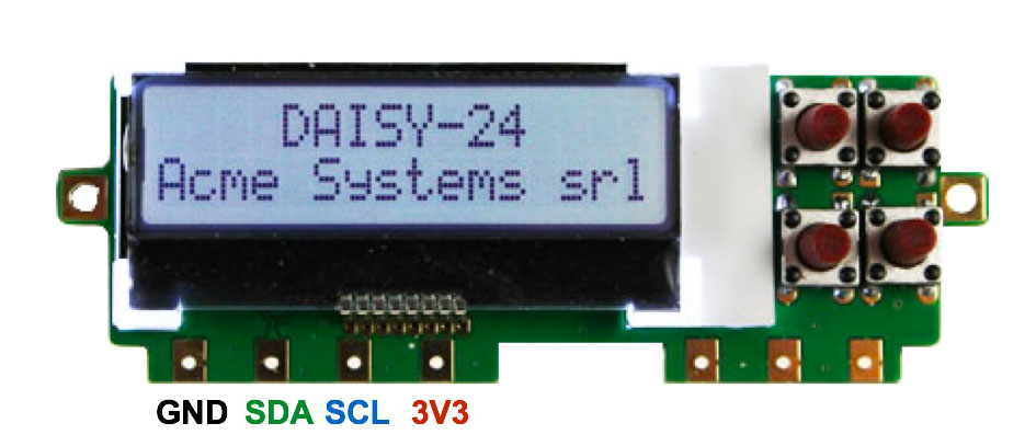
This is the list of wirings to link the DAISY-24 display to the YARM-DEV board:
| Yarm-dev pin # | SAM line | Signal | Daisy-24 |
|---|---|---|---|
| 14 | GND | GND | GND |
| 7 | PA8 (data line) | I2C-SDA | SDA |
| 8 | PA9 (clock line ) | I2C-SCL | SCL |
| 28 | 3V3 | 3V3 | 3V3 |
Code examples
In these examples we will use the Cledic's Yarm libraries available on GitHub
To install them in your Atmel Studio environment add
- Daisy24_lib.c
- Daisy24_lib.h
in the src folder of your project
Add also this minimal set of ASF library
Hello World !
#include <asf.h>
#include <stdint.h>
#include "Daisy24_lib.h"

int main(void)
{
	Daisy24_LCD_Init();
	delay_init();

	// Write "Hello World !"
	Daisy24_LCD_WriteString((char *)"Hello World !");
}
Set cursor position
#include <asf.h>
#include <stdint.h>
#include "Daisy24_lib.h"

int main( void)
{
	// Display init
	Daisy24_LCD_Init();
	delay_init();

	// Display clear
	Daisy24_LCD_Clear();

	// Set the cursor position to x=0,y=0 (top left) and write A
	Daisy24_LCD_SetCursor( 0, 0);
	Daisy24_LCD_WriteChar('A');

	// Set the cursor position to x=15,y=0 (top right) and write B
	Daisy24_LCD_SetCursor( 15, 0);
	Daisy24_LCD_WriteChar('B');

	// Set the cursor position to x=0,y=1 (bottom lefy) and write C
	Daisy24_LCD_SetCursor( 0, 1);
	Daisy24_LCD_WriteChar('C');

	// Set the cursor position to x=15,y=1 (bottom right) and write D
	Daisy24_LCD_SetCursor( 15, 1);
	Daisy24_LCD_WriteChar('D');

}
Backlight
#include <asf.h>
#include <stdint.h>
#include "Daisy24_lib.h"

int main( void)
{
	// Display init
	Daisy24_LCD_Init();
	delay_init();

	// Backlight off
	Daisy24_LCD_BkLightOff();
	Daisy24_LCD_SetCursor( 0, 0);
	Daisy24_LCD_WriteString((char *)"Backlight OFF");

	// Wait 1 secs
	delay_ms(2000);

	// Backlight on
	Daisy24_LCD_BkLightOn();
	Daisy24_LCD_SetCursor( 0, 0);
	Daisy24_LCD_WriteString((char *)"Backlight ON ");
}
If the backlight remains ON, change these lines in Daisy24_lib.c source.
//#define EXPANDER_I2C_ADDR       0x27    // PCF8574T
#define EXPANDER_I2C_ADDR       0x3F    // PCF8574AT
or viceversa
#define EXPANDER_I2C_ADDR       0x27    // PCF8574T
//#define EXPANDER_I2C_ADDR     0x3F    // PCF8574AT
The right address depends from the I2C expander chip mounted on your Daisy24 module.
Read push-buttons
#include <asf.h>
#include <stdint.h>
#include "Daisy24_lib.h"

int main( void)
{
	uint32_t p;

	// Display init
	Daisy24_LCD_Init();
	delay_init();

	Daisy24_LCD_WriteString((char *)"Press a button:");
	for (;;) {
		if (Daisy24_PB_Status(&p)==0) {
			if (p==0)  {
				Daisy24_LCD_SetCursor( 0, 1);
				Daisy24_LCD_WriteString((char *)"            ");
			}
			if 	(p==1) {
				Daisy24_LCD_SetCursor( 0, 1);
				Daisy24_LCD_WriteString((char *)"TOP LEFT    ");
			}
			if 	(p==2) {
				Daisy24_LCD_SetCursor( 0, 1);
				Daisy24_LCD_WriteString((char *)"TOP RIGHT   ");
			}
			if 	(p==8) {
				Daisy24_LCD_SetCursor( 0, 1);
				Daisy24_LCD_WriteString((char *)"BOTTOM LEFT ");
			}
			if 	(p==4) {
				Daisy24_LCD_SetCursor( 0, 1);
				Daisy24_LCD_WriteString((char *)"BOTTOM RIGHT");
			}
		}
	}
}
If nothing happen pressing the buttons, read how to change the I2C expander address in the backlight example.
Links
Buy
