Aria technical documentation Buy
SD or MicroSD memory card
Aria G25 can boot directly from an SD memory card.
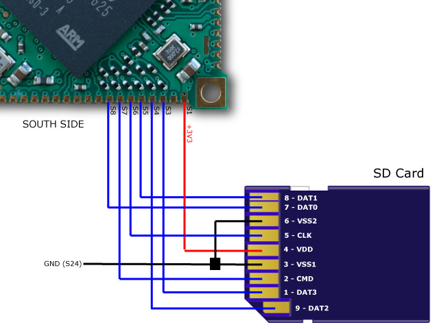
This is a simple wiring scheme to do that.

For a real project please follow this guide line:
Up to two SD card can be wired following this pinout:
| Primary SD (mmc0) | Secondary SD (mmc1) | SD card pins |
|---|---|---|
| S1 (3V3) | S1 (3V3) | 4 (VDD) |
| S3 (DA3 MMC0) | S19 (DA3 MMC1) | 1 (DAT3) |
| S4 (DA2 MMC0) | S20 (DA2 MMC1) | 9 (DAT2) |
| S5 (DA1 MMC0) | S21 (DA1 MMC1) | 8 (DAT1) |
| S6 (CK MMC0) | S10 (CK MMC1) | 5 (CLK) |
| S7 (CDA MMC0) | S11 (CDA MMC1) | 2 (CMD) |
| S8 (DA0 MMC0) | S12 (DA0 MMC1) | 7 (DAT0) |
| S24 (GND) | S24 (GND) | 3 (VSS1) and 6 (VSS2) |
This is the device tree definition to use:
mmc0: mmc@f0008000 {
    pinctrl-0 = <
        &pinctrl_mmc0_slot0_clk_cmd_dat0
        &pinctrl_mmc0_slot0_dat1_3>;
    status = "okay";
    slot@0 {
        reg = <0>;
        bus-width = <4>;
    };
};

mmc1: mmc@f000c000 {
    pinctrl-0 = <
        &pinctrl_mmc1_slot0_clk_cmd_dat0
        &pinctrl_mmc1_slot0_dat1_3>;
    status = "okay";
    slot@0 {
        reg = <0>;
        bus-width = <4>;
    };
};
MicroSD memory card
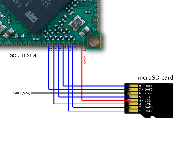
Aria G25 can boot directly from a uSD memory card. Up to two uSD card slots can be wired.
- To create a bootable class='acmetable' memory card follow this article
- To buy a ready to use memory card see our eShop.

Lines used:
| Primary uSD (mmc0) | Secondary uSD (mmc1) | uSD card pins |
|---|---|---|
| S1 (3V3) | S1 (3V3) | 4 (VDD) |
| S3 (DA3) | S19 (DA3) | 2 (DAT3) |
| S4 (DA2) | S20 (DA2) | 1 (DAT2) |
| S5 (DA1) | S21 (DA1) | 8 (DAT1) |
| S6 (CK) | S10 (CK) | 5 (CLK) |
| S7 (CDA) | S11 (CDA) | 3 (CMD) |
| S8 (DA0) | S12 (DA0) | 7 (DAT0) |
| S24 (GND) | S24 (GND) | 6 (VSS) |
This is the device tree definition to use:
mmc0: mmc@f0008000 {
    pinctrl-0 = <
        &pinctrl_mmc0_slot0_clk_cmd_dat0
        &pinctrl_mmc0_slot0_dat1_3>;
    status = "okay";
    slot@0 {
        reg = <0>;
        bus-width = <4>;
    };
};

mmc1: mmc@f000c000 {
    pinctrl-0 = <
        &pinctrl_mmc1_slot0_clk_cmd_dat0
        &pinctrl_mmc1_slot0_dat1_3>;
    status = "okay";
    slot@0 {
        reg = <0>;
        bus-width = <4>;
    };
};
To create a bootable class='acmetable' memory card follow this article:
To buy a ready to use memory buy on our Store:


