foxd27 technical documentation
Building a Linux Driver for WS2812B LED Strips over SPI
AI WARNING: This article and its content were created with SuperGrok version 4.5 and manually verified on the Fox Board D27.
1. The problem: a tight one-wire protocol
The WS2812B does not speak I2C or native SPI. It uses a single-wire serial protocol (DIN) where each bit is encoded by the duration of the high level on the wire:
| WS2812 bit | Typical waveform (≈800 kbit/s) |
|---|---|
| 0 | short high pulse, then low |
| 1 | long high pulse, then low |
At the end of the frame a reset is required (line held low for at least ~50 µs, often longer on clones) so the LEDs latch the colours and update their outputs.
On bare-metal microcontrollers this is often done with:
- timer/PWM + DMA, or
- bit-banging with interrupts disabled.
On Linux, bit-banging from the kernel with sub-microsecond timing is awkward: preemption, interrupts, and the scheduler easily break the timing windows. What is needed is a path where hardware generates the edges deterministically.
2. The key idea: simulate the protocol with SPI MOSI
The approach taken is a well-known embedded trick:
Encode each WS2812 bit as three SPI bits, and run SPI at about 2.4 MHz (i.e. 3 × 800 kHz).
The MOSI line then reproduces the high/low pulses the LED expects:
WS2812 bit 0  →  SPI  1 0 0   (short high)
WS2812 bit 1  →  SPI  1 1 0   (long high)
In the code:
#define WS2812B_SPI_HZ      2400000
#define WS2812B_CODE_0      0x4   /* 0b100 */
#define WS2812B_CODE_1      0x6   /* 0b110 */
One colour byte (8 bits) therefore becomes 24 SPI bits = 3 SPI bytes:
1 colour byte × 3 SPI bits/bit = 24 SPI bits = 3 bytes in the TX buffer
One RGB LED (3 channels) uses 9 SPI data bytes, plus a trailer of zeros for the reset.
Why not GPIO bit-bang?
| Approach | Pros | Cons |
|---|---|---|
| GPIO bit-bang | Easy to explain | Fragile timing under Linux, CPU busy |
| SPI + encoding | Hardware clock, DMA, CPU free | Needs an SPI controller and a dedicated MOSI |
On the SAMA5D2, the SPI controller (including the one exposed via Flexcom) enables XDMAC for transfers of 16 bytes or more. A single expanded LED already exceeds that threshold → every real refresh goes through DMA.
3. Driver architecture
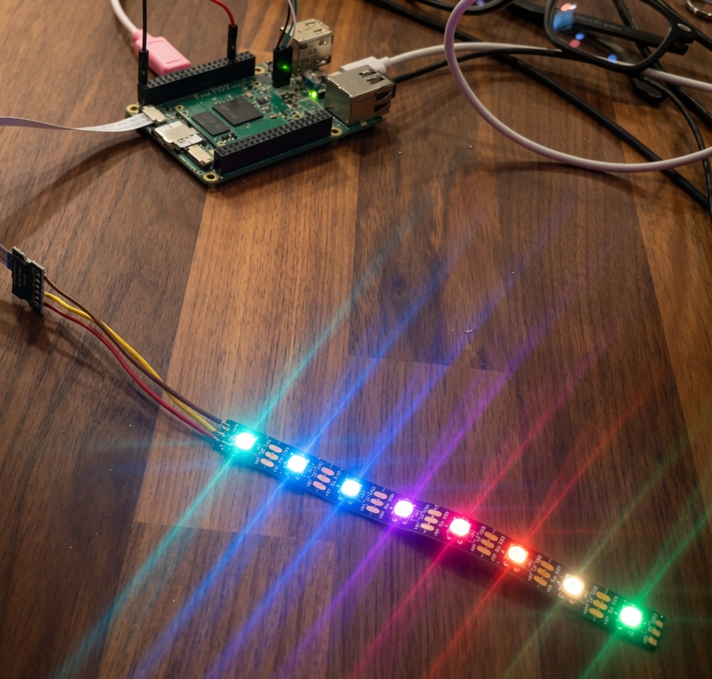
The driver is not a multi-colour led_classdev for a single LED, but an SPI client that exposes a misc character device (/dev/ws2812b) designed for whole strips.
┌─────────────┐    write RGB     ┌──────────────────────┐
│  Userspace  │ ───────────────► │  /dev/ws2812b        │
│  (printf,   │                  │  miscdevice          │
│   Python…)  │ ◄─────────────── │  read → current RGB  │
└─────────────┘                  └──────────┬───────────┘
                                            │
                    RGB → GRB               │
                    encode 1→3 SPI bits     ▼
                                 ┌──────────────────────┐
                                 │  spi_buf (DMA-safe)  │
                                 │  + reset trailer     │
                                 └──────────┬───────────┘
                                            │ spi_sync()
                                            ▼
                                 ┌──────────────────────┐
                                 │  spi-atmel + XDMAC   │
                                 │  MOSI @ 2.4 MHz      │
                                 └──────────┬───────────┘
                                            │
                                            ▼
                                      WS2812B DIN
Private structure
struct ws2812b_priv {
    struct spi_device   *spi;
    struct mutex        lock;
    struct miscdevice   miscdev;

    u32                 num_leds;
    u8                  *pixels;     /* wire order: GRB */
    u8                  *spi_buf;    /* SPI stream + reset */
    size_t              spi_buf_len;
};
Two distinct buffers:
pixels— logical strip state in GRB order (what the chip wants).spi_buf— frame already expanded into SPI bits, ready forspi_sync(), allocated withGFP_DMAto favour DMA mapping on ARM.
4. Encoding: from colour byte to SPI bitstream
The core function is ws2812b_encode_byte():
static void ws2812b_encode_byte(u8 *dst, u8 val)
{
    u32 bits = 0;
    int i;

    for (i = 7; i >= 0; i--) {          /* MSB first, as WS2812 requires */
        bits <<= 3;
        bits |= (val & BIT(i)) ? WS2812B_CODE_1 : WS2812B_CODE_0;
    }

    dst[0] = (bits >> 16) & 0xff;
    dst[1] = (bits >> 8)  & 0xff;
    dst[2] =  bits        & 0xff;
}
Example: colour 0xFF (all bits one) → eight times the pattern 110, packed into three SPI bytes.
The full frame is built as follows:
static void ws2812b_encode_frame(struct ws2812b_priv *priv)
{
    /* for each GRB byte → 3 SPI bytes */
    ...
    /* trailer: MOSI low → reset / latch */
    memset(out, 0, WS2812B_RESET_BYTES);  /* 96 bytes ≈ 320 µs @ 2.4 MHz */
}
A trailer of 96 zero bytes holds MOSI low long enough (~300 µs) to satisfy both the official datasheet (≥50 µs) and many more demanding clones.
5. Colour order: RGB in userspace, GRB on the wire
The WS2812B expects channels in G, R, B order, not R, G, B.
To avoid forcing applications to remember that, the userspace interface stays natural RGB:
/* write from userspace: R,G,B,R,G,B,... */
priv->pixels[i * 3 + 0] = g;
priv->pixels[i * 3 + 1] = r;
priv->pixels[i * 3 + 2] = b;
On read (read on /dev/ws2812b) the inverse GRB → RGB conversion is applied, so a round-trip is consistent.
Useful behaviour: if fewer LEDs than configured are written, the remaining ones are turned off (buffer zeroed). Only multiples of 3 bytes (whole LEDs) are accepted.
6. Transmission: one spi_sync() per frame
static int ws2812b_flush(struct ws2812b_priv *priv)
{
    struct spi_transfer xfer = {
        .tx_buf        = priv->spi_buf,
        .len           = priv->spi_buf_len,
        .speed_hz      = WS2812B_SPI_HZ,
        .bits_per_word = 8,
    };
    struct spi_message msg;

    ws2812b_encode_frame(priv);
    spi_message_init(&msg);
    spi_message_add_tail(&xfer, &msg);

    return spi_sync(priv->spi, &msg);
}
No queue of tiny transfers, no software bit-by-bit loop on the bus: one SPI message, one continuous buffer. On the spi-atmel path this enables DMA (DMA_MIN_BYTES = 16 in spi-atmel.c).
Typical buffer sizes:
| LEDs | SPI data | + reset | Total |
|---|---|---|---|
| 1 | 9 bytes | 96 | 105 |
| 8 | 72 bytes | 96 | 168 |
| 1024 | 9216 | 96 | 9312 |
Soft limit in the driver: 1024 LEDs (WS2812B_MAX_LEDS).
7. Userspace interface: /dev/ws2812b
In probe a miscdevice is registered with a dynamic minor:
priv->miscdev.name  = "ws2812b";
priv->miscdev.fops  = &ws2812b_fops;
misc_register(&priv->miscdev);
| Operation | Effect |
|---|---|
write |
Copy RGB, convert to GRB, encode SPI, flush the strip |
read |
Return current RGB state (from offset) |
sysfs num_leds |
Strip length (read-only) |
Practical examples:
# 8 LEDs all red
printf '\xff\x00\x00\xff\x00\x00\xff\x00\x00\xff\x00\x00\xff\x00\x00\xff\x00\x00\xff\x00\x00\xff\x00\x00' \
  > /dev/ws2812b

# First LED green only, rest off
printf '\x00\xff\x00' > /dev/ws2812b

# How many LEDs are configured
cat /sys/class/misc/ws2812b/num_leds
In Python:
n = 8
rgb = bytearray(n * 3)
rgb[0:3] = bytes([0, 0, 255])  # first LED blue
open('/dev/ws2812b', 'wb').write(rgb)
Choosing a raw char device instead of the LED class framework alone makes multi-pixel animations and frame buffers from userspace straightforward (one write = one full frame).
8. Probe, Device Tree, and foxd27 hardware
Binding
ws2812b@0 {
    compatible = "worldsemi,ws2812b-spi";
    reg = <0>;
    spi-max-frequency = <2400000>;
    num-leds = <8>;   /* or "chain-length" as an alias */
};
Accepted compatibles: worldsemi,ws2812b-spi and acme,ws2812b-spi.
Pins on Acme RoadRunner / test DT (acme-test.dts)
FLEXCOM2 is used in SPI mode:
| Pin | Flexcom function | Use |
|---|---|---|
| PD26 | FLEXCOM2_IO0 (MOSI) | strip DIN |
| PD27 | FLEXCOM2_IO1 (MISO) | unused by LEDs |
| PD28 | FLEXCOM2_IO2 (SPCK) | SPI clock (required by controller) |
| PD30 | GPIO CS | chip-select; not to the LED |
Important wiring notes:
- Only MOSI → DIN reaches the strip, plus a shared GND.
- SPCK and CS must not be wired to the LED data line.
- Power the LEDs from a suitable class='acmetable' 5 V supply; for long strips a 3.3 V → 5 V level shifter on DIN is recommended.
- PD26/PD27 cannot be I2C and SPI at the same time: the test DT dedicates them to SPI/WS2812B.
In probe:
- Read
num-leds(default 8). - Allocate pixel and SPI buffers.
- Force SPI mode 0, 8 bits, 2.4 MHz (
spi_setup). - Clear the strip with an initial flush.
- Register
/dev/ws2812b.
In remove, clear the strip again and deregister the misc device.
9. Integration in the kernel tree
| File | Role |
|---|---|
drivers/leds/leds-ws2812b-spi.c |
Implementation |
drivers/leds/Kconfig |
CONFIG_LEDS_WS2812B_SPI (depends on SPI + OF) |
drivers/leds/Makefile |
obj-$(CONFIG_LEDS_WS2812B_SPI) += leds-ws2812b-spi.o |
arch/arm/boot/dts/acme-ws2812b.dts |
Flexcom2 + SPI node example |
Typical build:
make ARCH=arm CROSS_COMPILE=arm-linux-gnueabihf- acme-foxd27_defconfig
# enable LEDS_WS2812B_SPI in menuconfig (Device Drivers → LED Support)
make ARCH=arm CROSS_COMPILE=arm-linux-gnueabihf- -j$(nproc)
make ARCH=arm CROSS_COMPILE=arm-linux-gnueabihf- dtbs
The module is named leds-ws2812b-spi when built as =m; with =y it is built-in.
10. End-to-end data path (operational summary)
- The application writes
N×3RGB bytes to/dev/ws2812b. - The driver takes the mutex, copies the data, converts to GRB in
pixels. ws2812b_encode_frameexpands each bit to pattern100/110and appends 96 zero bytes for reset.spi_syncsends the whole buffer at 2.4 MHz.- The Atmel SPI controller programs XDMAC: the CPU does not generate the bits.
- MOSI produces the one-wire waveform; the LEDs sample it and, after reset, update their internal PWMs.
The mutex plus synchronous spi_sync prevent overlapping frames and races when multiple processes write the device at once.
11. Design choices and trade-offs
What works well
- Reliable timing under system load, thanks to SPI + DMA.
- Trivial userspace API (write bytes).
- Easy to port to other SoCs with SPI and DMA (need ~2.4 MHz clock and a clean MOSI).
- RGB↔GRB conversion hidden in the kernel.
Limits to keep in mind
- Occupies the SPI bus and dedicated pins (MOSI required; SPCK is needed by the controller even if not wired to the LED).
- A full frame is synchronous: high-refresh animations with thousands of LEDs cost memory and bus time.
- No global hardware brightness or gamma correction — do that in userspace if needed.
- The CS GPIO exists because the SPI master requires it, but it is not part of the WS2812B protocol.
12. Conclusion
The leds-ws2812b-spi driver starts from the problem of deterministic timing on Linux and solves it by turning the WS2812B one-wire protocol into a 2.4 MHz SPI stream, 3:1 encoded, sent in a single shot via DMA on the SAMA5D2.
From the application side it remains as simple as:
echo -ne '\xff\x00\x00' > /dev/ws2812b
Behind that write: RGB→GRB conversion, bit packing, reset trailer, and one SPI transfer mapped onto XDMAC — without userspace needing to know anything about the electrical protocol.
Sources
- Driver:
drivers/leds/leds-ws2812b-spi.c - Device tree:
arch/arm/boot/dts/acme-ws2812b.dts