How to design the LCD circuitry
Introduction
In the SAMA5D27 datasheet there is a complete and deep description of the LCD peripheral features. Below a short summary.
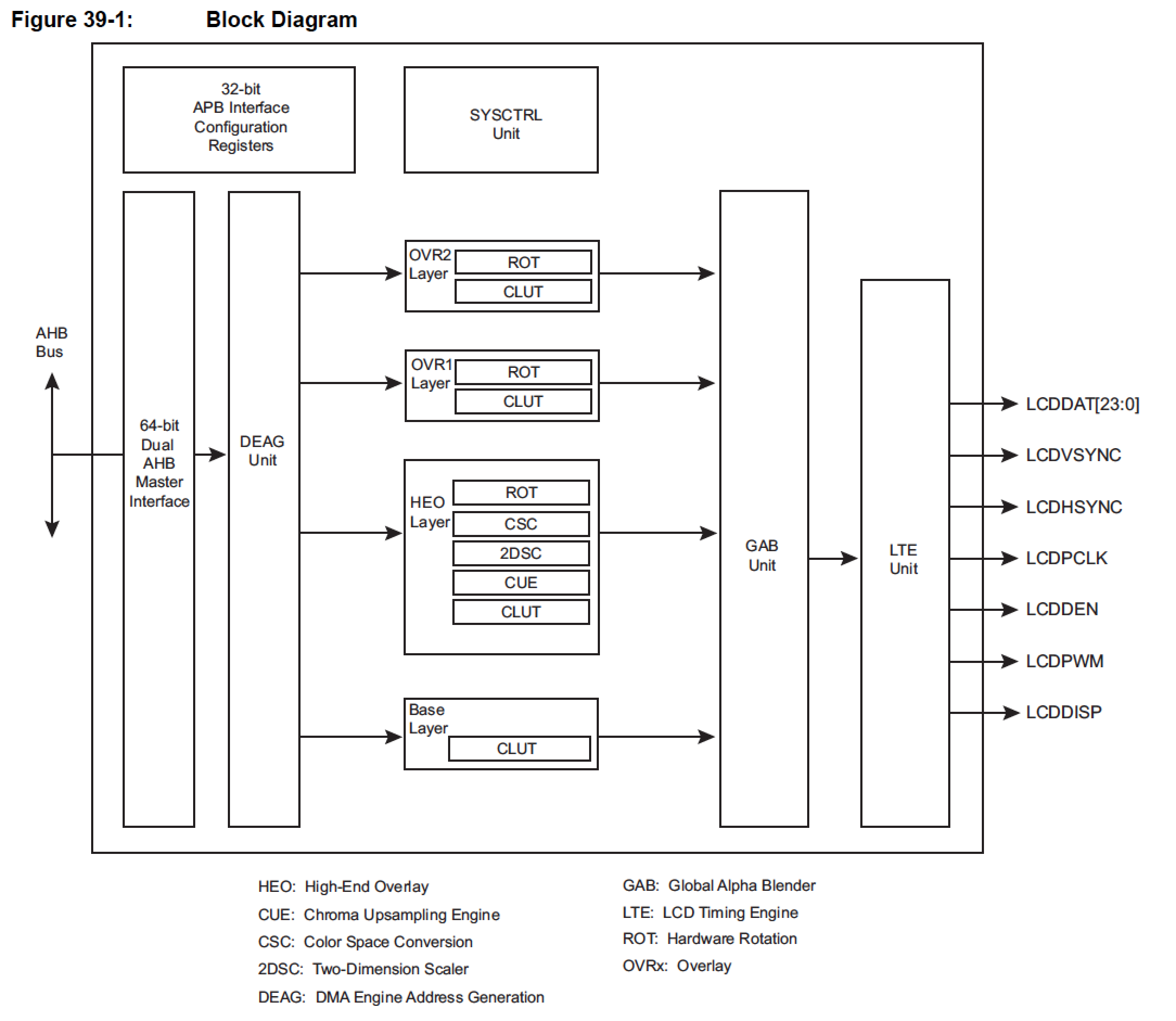
39.1 Description
The LCD Controller (LCDC) consists of logic for transferring LCD image data from an external display buffer to an LCD module. The LCD has one display input buffer per overlay that fetches pixels through the dual AHB master interface and a lookup table class='acmetable' to allow palletized display configurations. The LCD controller is programmable on a per overlay basis, and supports different LCD resolutions, window sizes, image formats and pixel depths.
The LCD is connected to the ARM Advanced High Performance Bus (AHB) as a master for reading pixel data. It also integrates an APB interface to configure its registers.
Pinout
The Roadrunner pins involved on LCD control are highlighted in the diagram (click to enlarge).
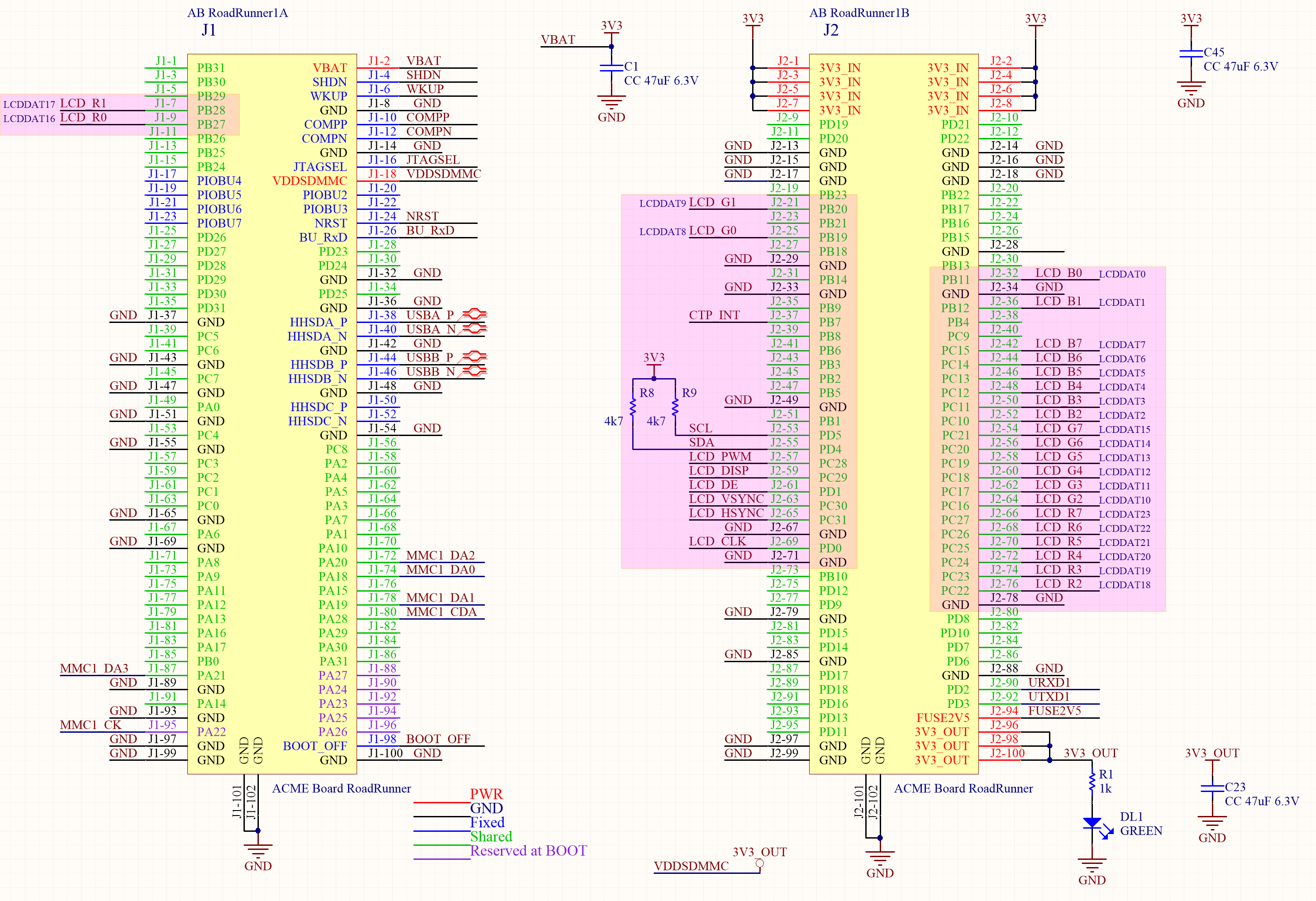
The block diagram and the table class='acmetable's below explain the meaning of the I/O needed to interface a standard LCD panel.
As many other peripherals, the same function can be addressed to different pins in order to have more flexibility on sharing the I/Os and on routing the PCB.
LCD Controller - LCDC
| Signal Name | Function | Type | PIN | alt. PIN |
|---|---|---|---|---|
| LCDDAT[23:0] | LCD 24-bit data bus | Output | see table class='acmetable' | see table class='acmetable' |
| LCDVSYNC | Vertical Synchronization Pulse | Output | PC30 | PC5 |
| LCDHSYNC | Horizontal Synchronization Pulse | Output | PC31 | PC6 |
| LCDPCK | Pixel Clock | Output | PD0 | PC7 |
| LCDDEN | Data Enable | Output | PD1 | PC8 |
| LCDPWM | Contrast control signal, using Pulse Width Modulation | Output | PC28 | PC3 |
| LCDDISP | Display Enable signal | Output | PC29 | PC4 |
According to the LCD panel configuration, the parallel bus can be used in different ways. In the following table class='acmetable' there is the description on how to route the pins to the LCD panel connector.
Active Mode Output with 24-bit Bus Interface Configuration
| Pin ID | TFT 24 bits | TFT 18 bits | TFT 16 bits | TFT 12 bits | PIN | alt. PIN |
|---|---|---|---|---|---|---|
| LCDDAT[23] | R[7] | R[5] | R[4] | R[3] | PC27 | PC2 |
| LCDDAT[22] | R[6] | R[4] | R[3] | R[2] | PC26 | PC1 |
| LCDDAT[21] | R[5] | R[3] | R[2] | R[1] | PC25 | PC0 |
| LCDDAT[20] | R[4] | R[2] | R[1] | R[0] | PC24 | PB31 |
| LCDDAT[19] | R[3] | R[1] | R[0] | – | PC23 | PB30 |
| LCDDAT[18] | R[2] | R[0] | – | – | PC22 | PB29 |
| LCDDAT[17] | R[1] | – | – | – | PB28 | - |
| LCDDAT[16] | R[0] | – | – | – | PB27 | - |
| LCDDAT[15] | G[7] | G[5] | G[5] | G[3] | PC21 | PB26 |
| LCDDAT[14] | G[6] | G[4] | G[4] | G[2] | PC20 | PB25 |
| LCDDAT[13] | G[5] | G[3] | G[3] | G[1] | PC19 | PB24 |
| LCDDAT[12] | G[4] | G[2] | G[2] | G[0] | PC18 | PB23 |
| LCDDAT[11] | G[3] | G[1] | G[1] | – | PC17 | PB22 |
| LCDDAT[10] | G[2] | G[0] | G[0] | – | PC16 | PB21 |
| LCDDAT[9] | G[1] | – | – | – | PB20 | - |
| LCDDAT[8] | G[0] | – | – | – | PB19 | - |
| LCDDAT[7] | B[7] | B[5] | B[4] | B[3] | PC15 | PB18 |
| LCDDAT[6] | B[6] | B[4] | B[3] | B[2] | PC14 | PB17 |
| LCDDAT[5] | B[5] | B[3] | B[2] | B[1] | PC13 | PB16 |
| LCDDAT[4] | B[4] | B[2] | B[1] | B[0] | PC12 | PB15 |
| LCDDAT[3] | B[3] | B[1] | B[0] | – | PC11 | PB14 |
| LCDDAT[2] | B[2] | B[0] | – | – | PC10 | PB13 |
| LCDDAT[1] | B[1] | – | – | – | PB12 | - |
| LCDDAT[0] | B[0] | – | – | – | PB11 | - |
Example
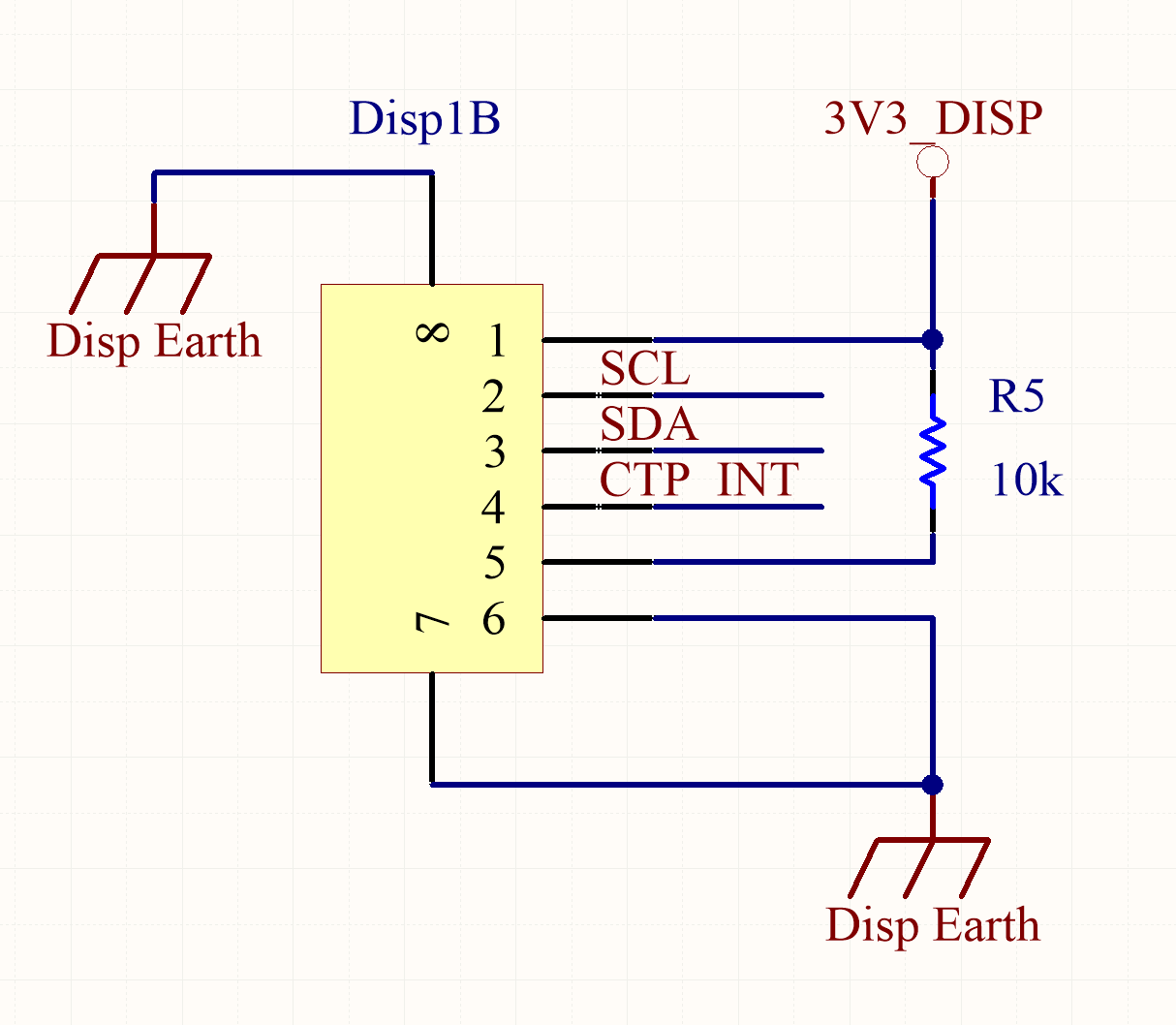
Let's show an example with a 5" LCD panel with a Capacitive Touch Panel
This is a 24-bit LCD and uses an FPC40 (Flexible Printed Circuit) to be connected with a standard FPC40 connector.
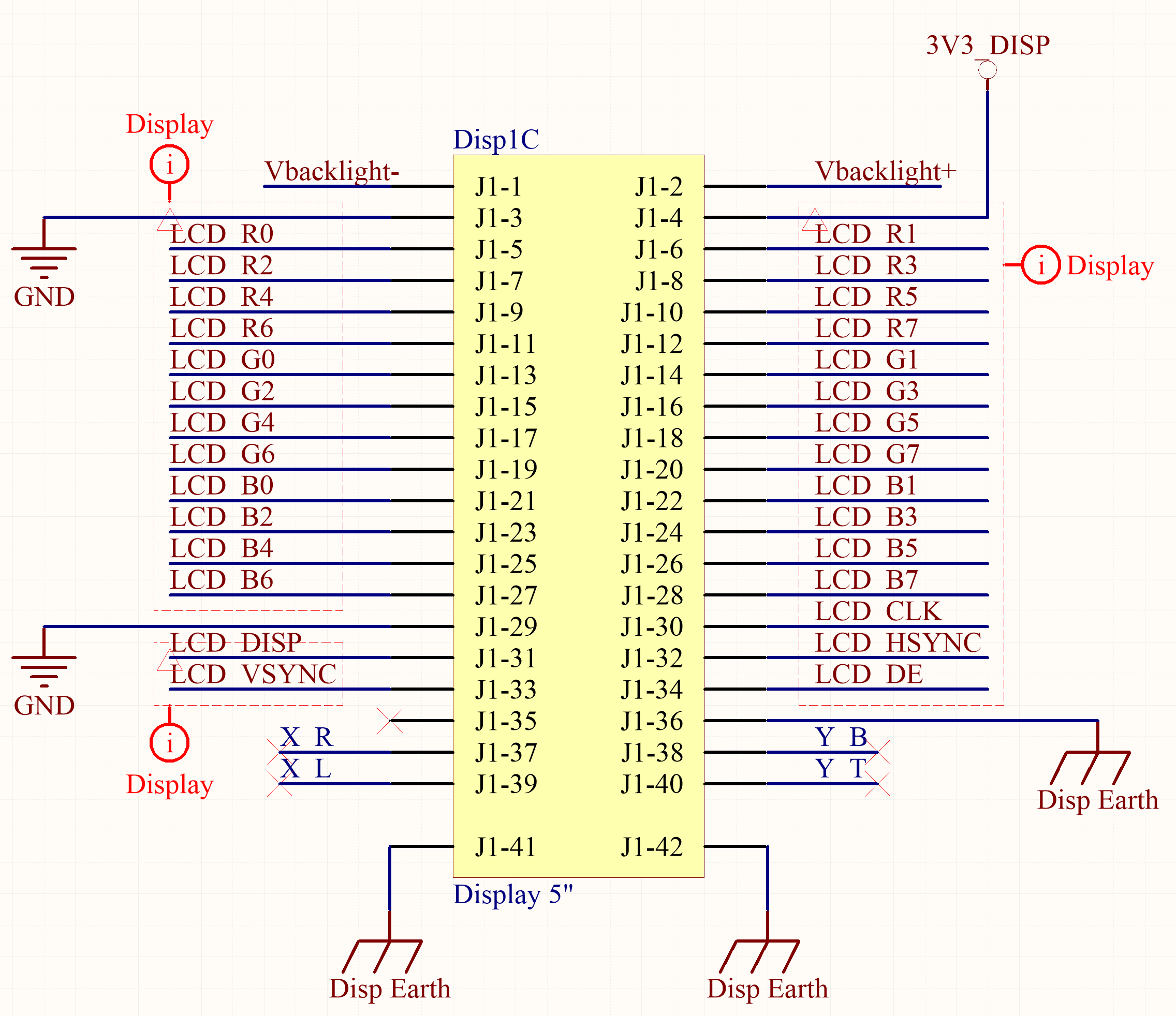
This kind of sockets is available in different configurations. They must be carefully chosen according to the specific usage. In the following example the LCD panel is mounted on the bottom layer and the flat cables are folded on the top layer reversing the contacts. In this case the FPC40 socket has contacts on top while the FPC6 (Capacitive Touch Panel socket) exposes the contacts on the bottom. Read carefully the datasheet or, better, look directly at a physical LCD sample before choosing the sockets and start the PCB routing.
Touch Screen
Capacitive
This example uses a Capacitive Touch Panel (CTP). This integrates the whole logic to returns touch information on an I2C bus interfaced through a FPC6 socket.
Resistive
The ADC peripheral of the SAMA5D27 MCU can also be used to interface a cheaper resistive touch panel in the 4 or 5 wire mode, according to the chosen model.
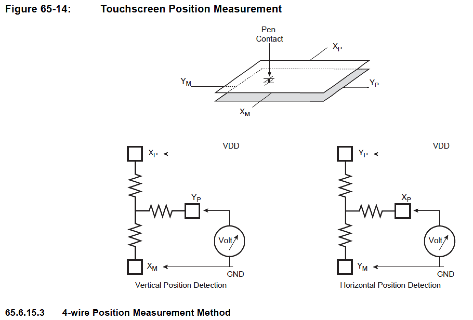
65.6.15.1 Touchscreen Mode
The TSMODE parameter of the ADC Touchscreen Mode register (ADC_TSMR) is used to enable/disable the touchscreen functionality, to select the type of screen (4-wire or 5-wire) and, in the case of a 4-wire screen and to activate (or not) the pressure measurement.
In 4-wire mode, channel 0, 1, 2 and 3 must not be used for classic ADC conversions. Likewise, in 5-wire mode, channel 0, 1, 2, 3, and 4 must not be used for classic ADC conversions.
A brief explanation of the 4-wire position measurement method:
Backlight power supply
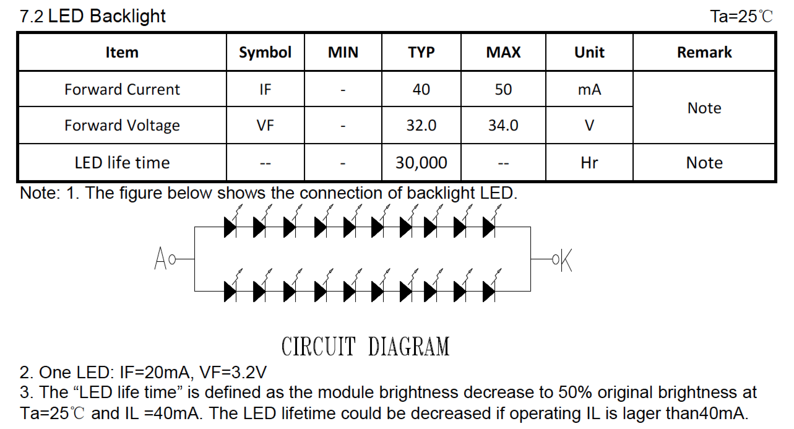
The backlight panel too follows a de-facto standard; it's lighted by a series-parallel of a number of high brightness LEDs sufficient to guarantee a good Luminance Uniformity. Because the usual Forward Voltage of such LEDs is 3.2V @ 20mA and the standard maximum voltage used is about 32V, with the chosen example it derives a 32V, 40mA power supply needed for 2x10 LEDs.
A high efficiency boost converter AP5727 from Diodes incorporated is used in the circuit diagram below.
The 33.2Ohm shunt resistor R23 returns the 1.25V reference needed by this regulator as feedback:
1.25V / 33.2Ohm = 37.65mA
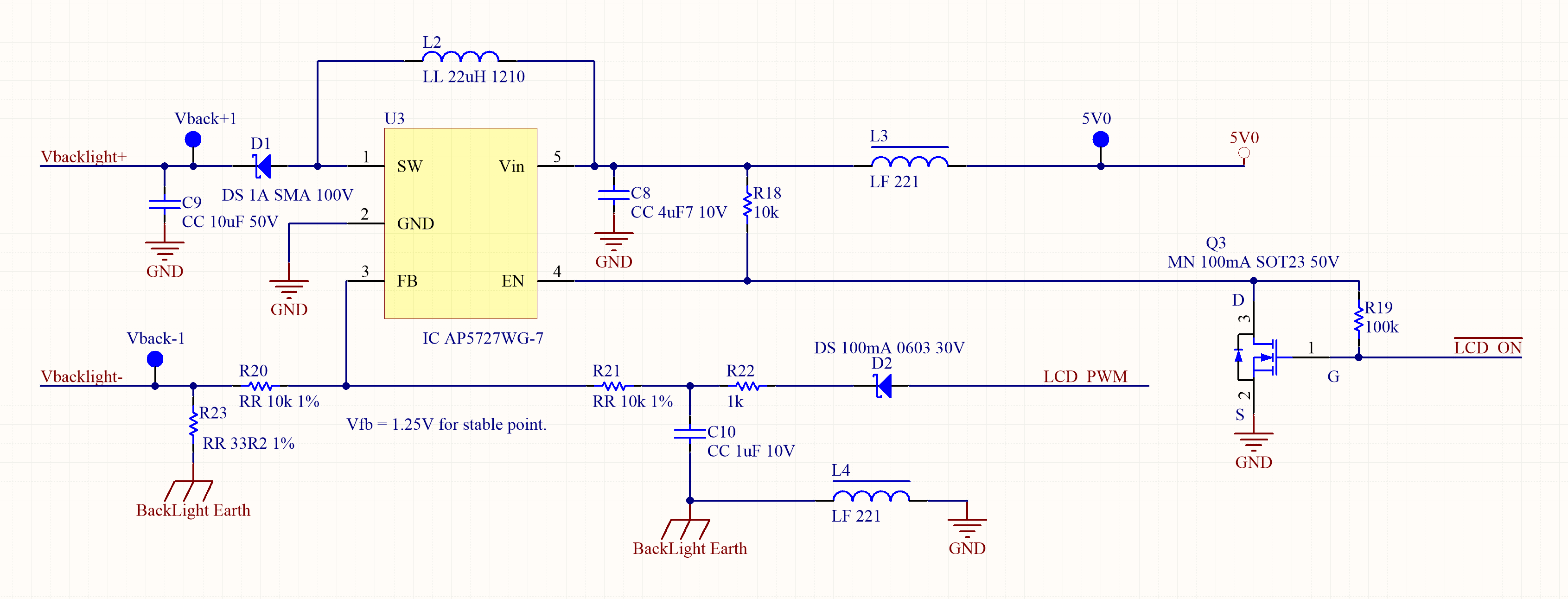
A filtered PWM signal is used as a variable DC voltage to control the LEDs current. The picture shows the PWM control circuitry connected to the FB pin. The PWM signal has a voltage swing of 0 V to 2.5 V and is added to the feedback voltage trough R20 and R21 resistors. The LEDs current can be dimmed from 0 to max current. The PWM signal frequency can vary from very low frequency up to 100 kHz. A PWM signal at 0 V DC, or a 0% duty cycle, results in a max LEDs current. A PWM signal with a 93% duty cycle or more, results in an LEDs current of 0 mA.
PCB
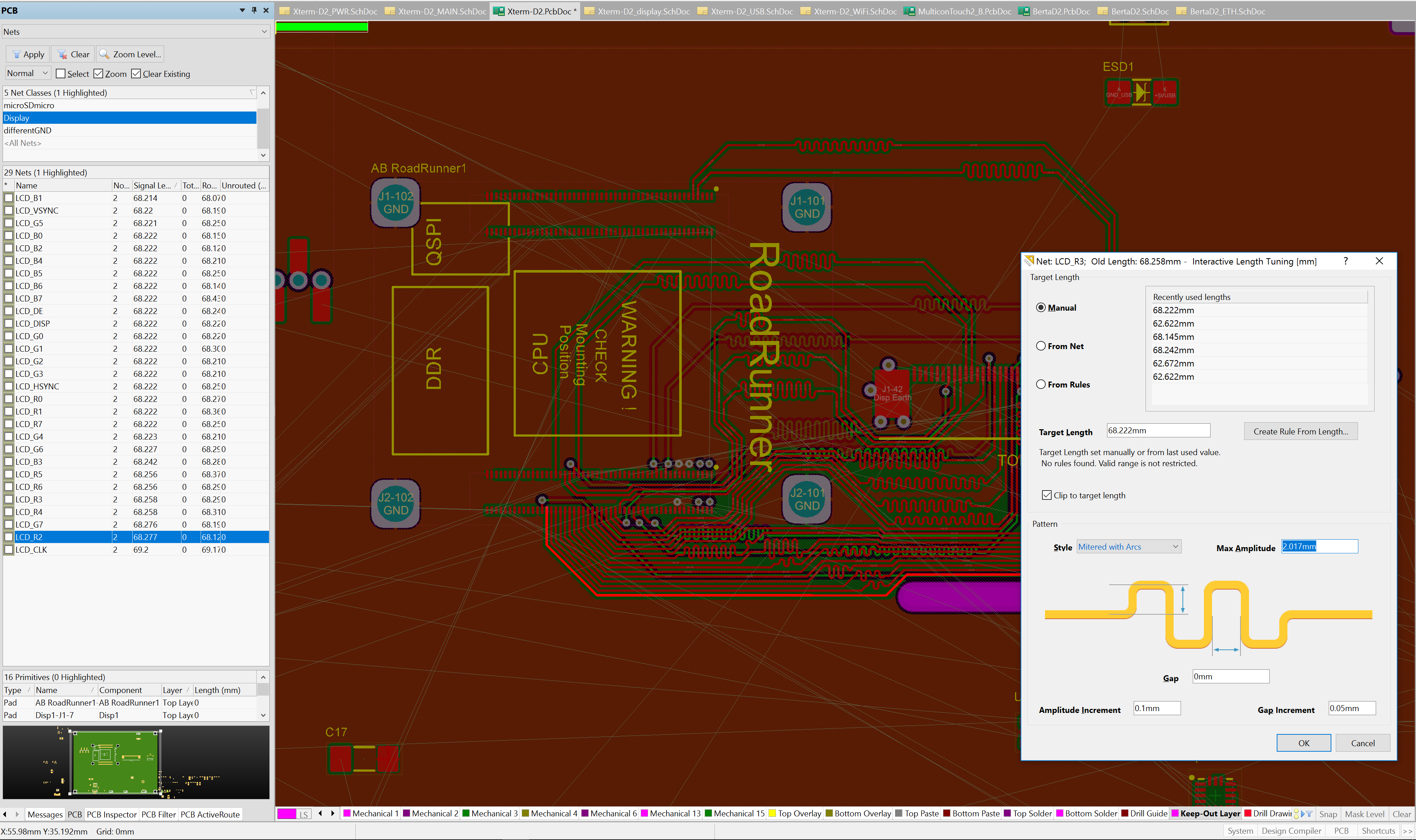
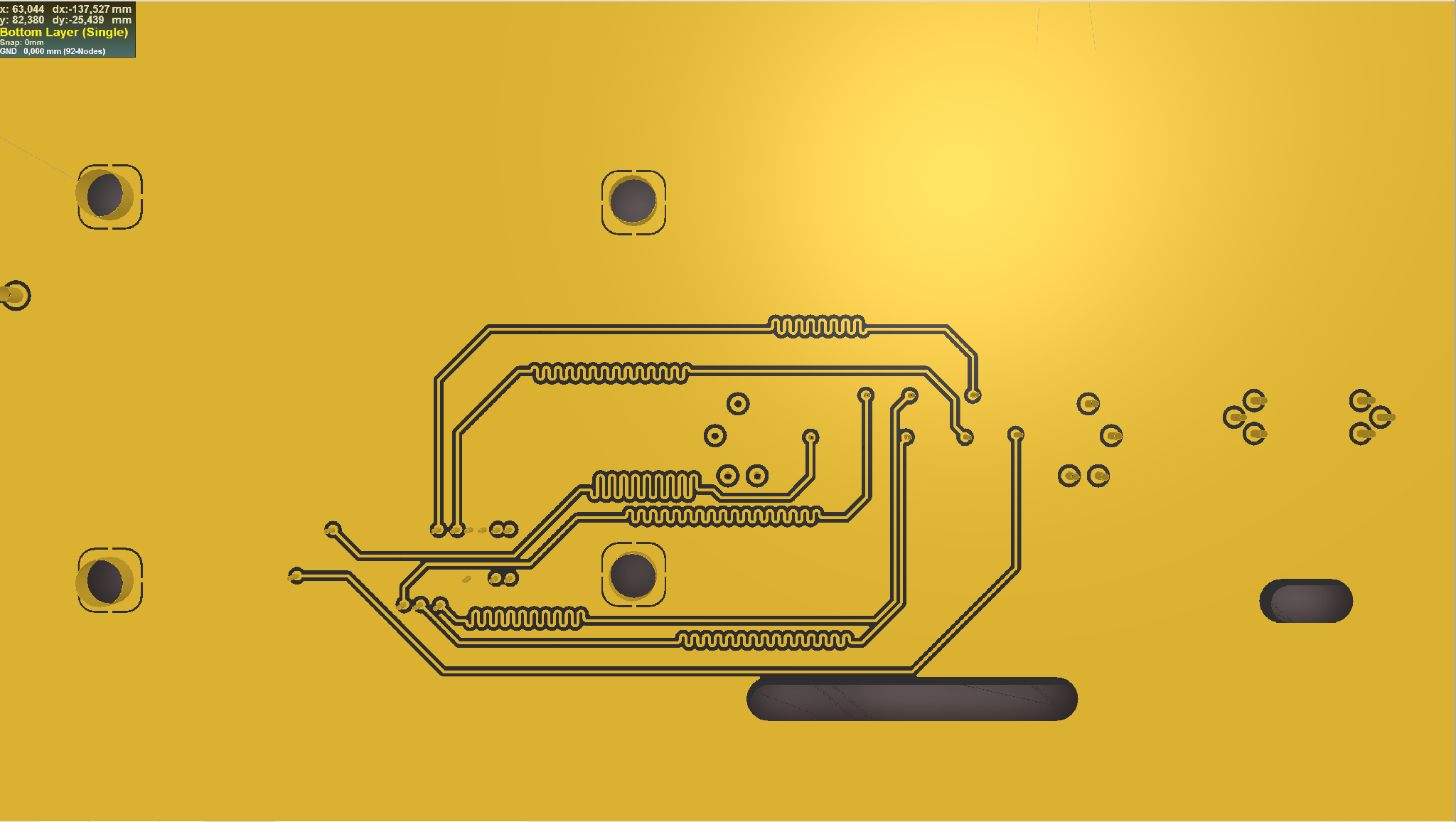
The display is driven with parallel signals. Those signals must feed the circuitry all at the same time to avoid flickering or any other kind of artifacts. So it's important that the tracks match in length each other in order to have the same travelling time. The clock signal line only have to be a little bit longer to guarantee that all the other signals are stable class='acmetable' at the right value when the clock triggers the frame.
Because the display lines are grouped in the same net class they can be matched using the PCB net classes view and the Interactive Length Tuning tool, as shown in the picture, adding an accordion to the lines to reach the length of the longest one.
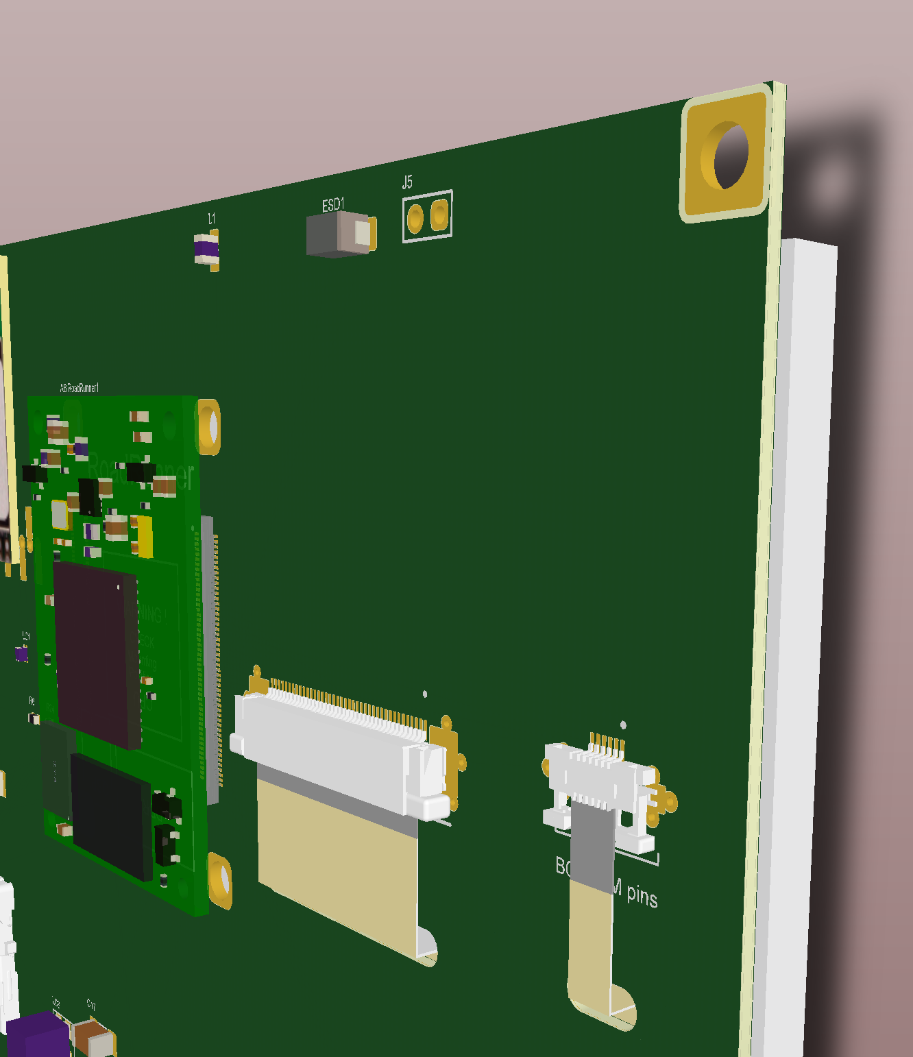
A 3D view of the PCB with the example abovementioned after routing and length matching
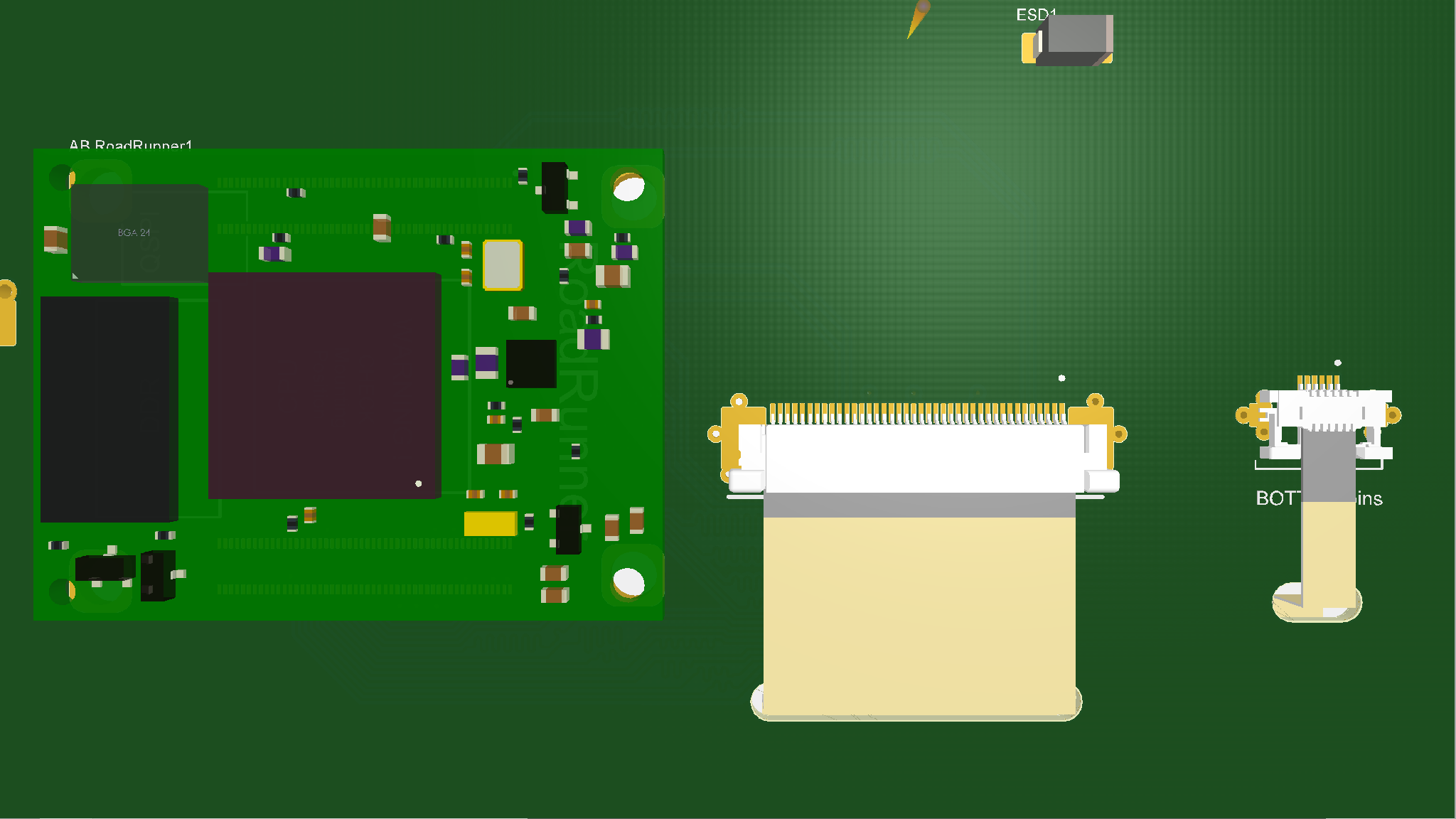
without components
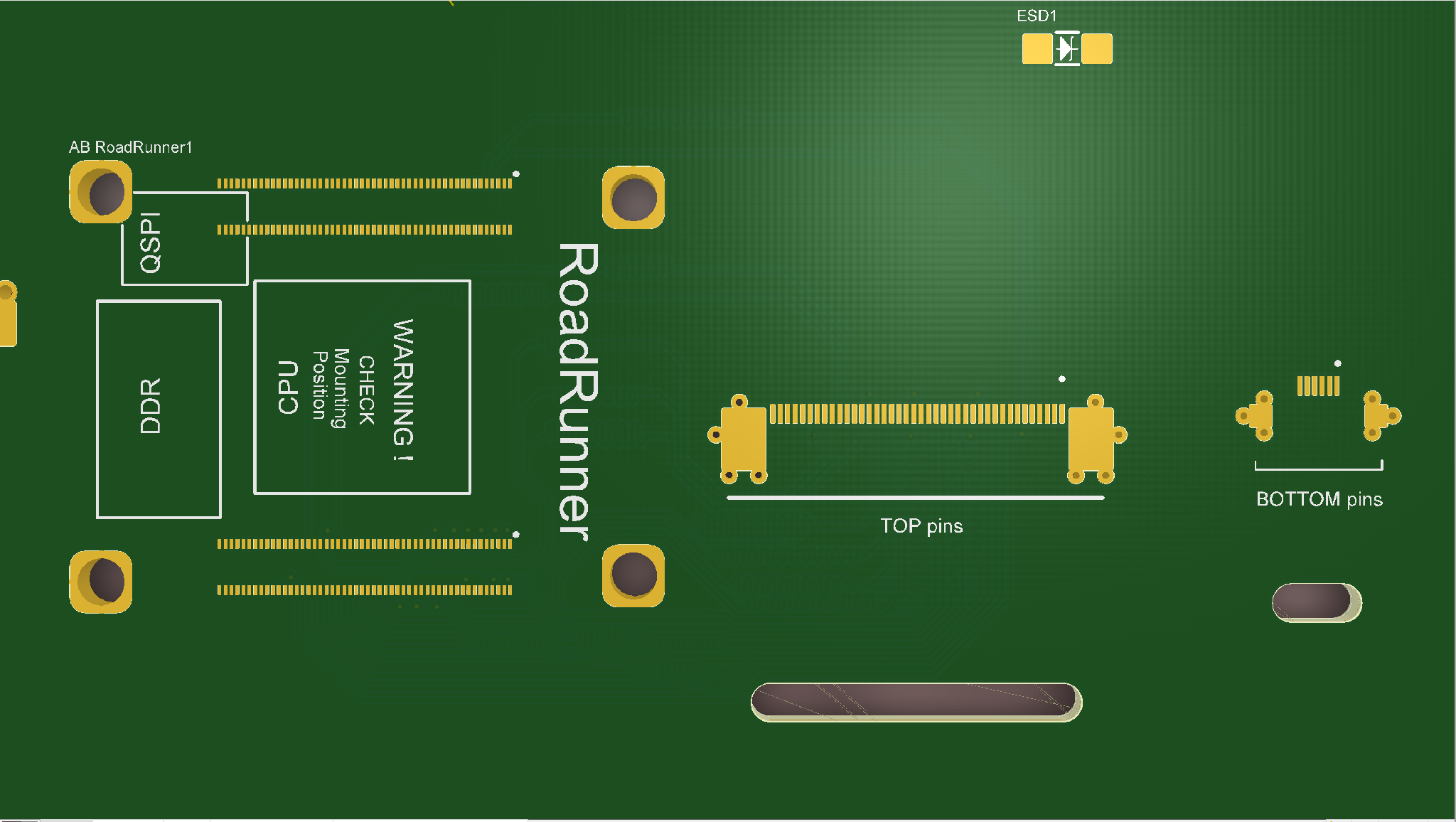
Top layer tracks view
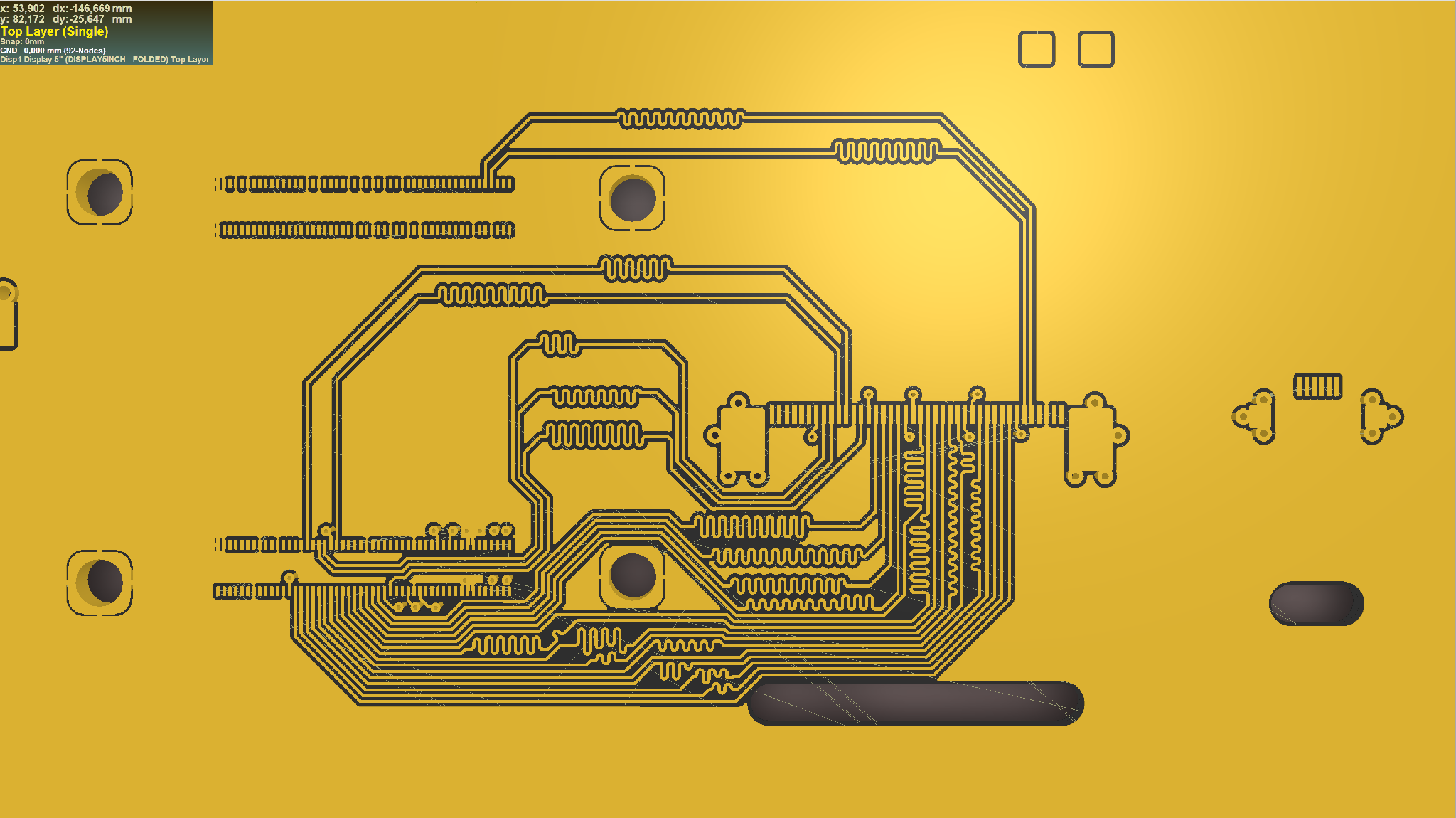
Bottom layer tracks view
If the components placement on PCB requires to route the tracks on external (top or bottom) and internal planes at the same time, the match must be done keeping in mind the different propagation delay between the two different conditions. The propagation delay on external planes can be calculated with the stripline formulas. It's lower, resulting in an equivalent shorter path.
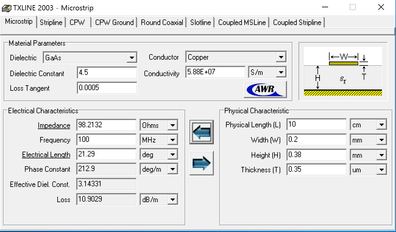
The stripline propagation delay depends on several factors and must be calculated for the specific parameters.
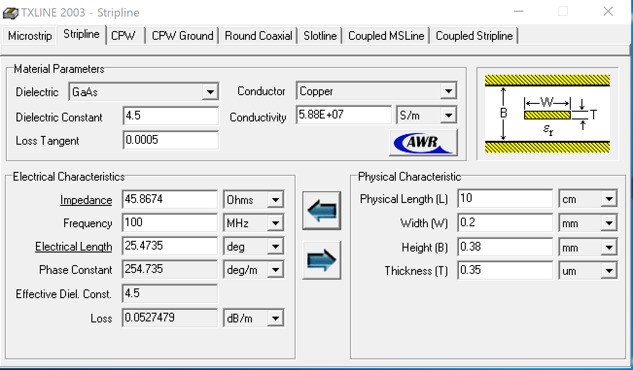
This leads to a percentage difference on the two signal lenghts that must be compensated adding the same percentage to the external tracks length.
Tap wake up
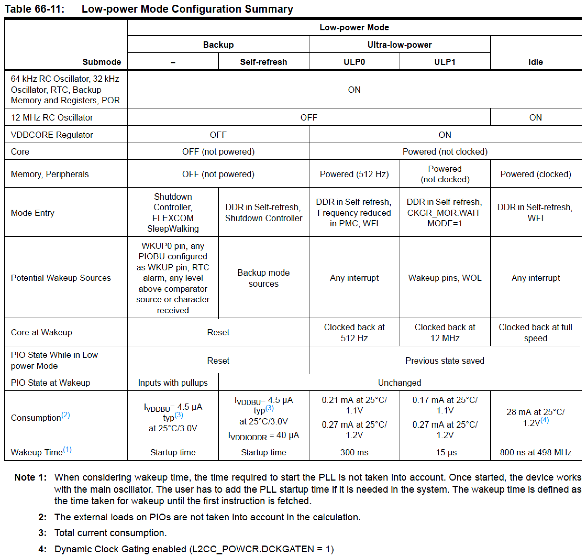
Despite its capabilities, the Roadrunner requires very low power.
Here a summary of the real life power consumption
When not in use, the best tradeoff between consumption and resuming time can be realized in different situations using one of the possible Low-power modes
Using the Roadrunner SOM Shutdown Controller (SHDWC) input and output pins available on the socket, also external devices (like the display and its backlight) can be switched on and off at your choice to get a very low power sleep mode for the whole system.
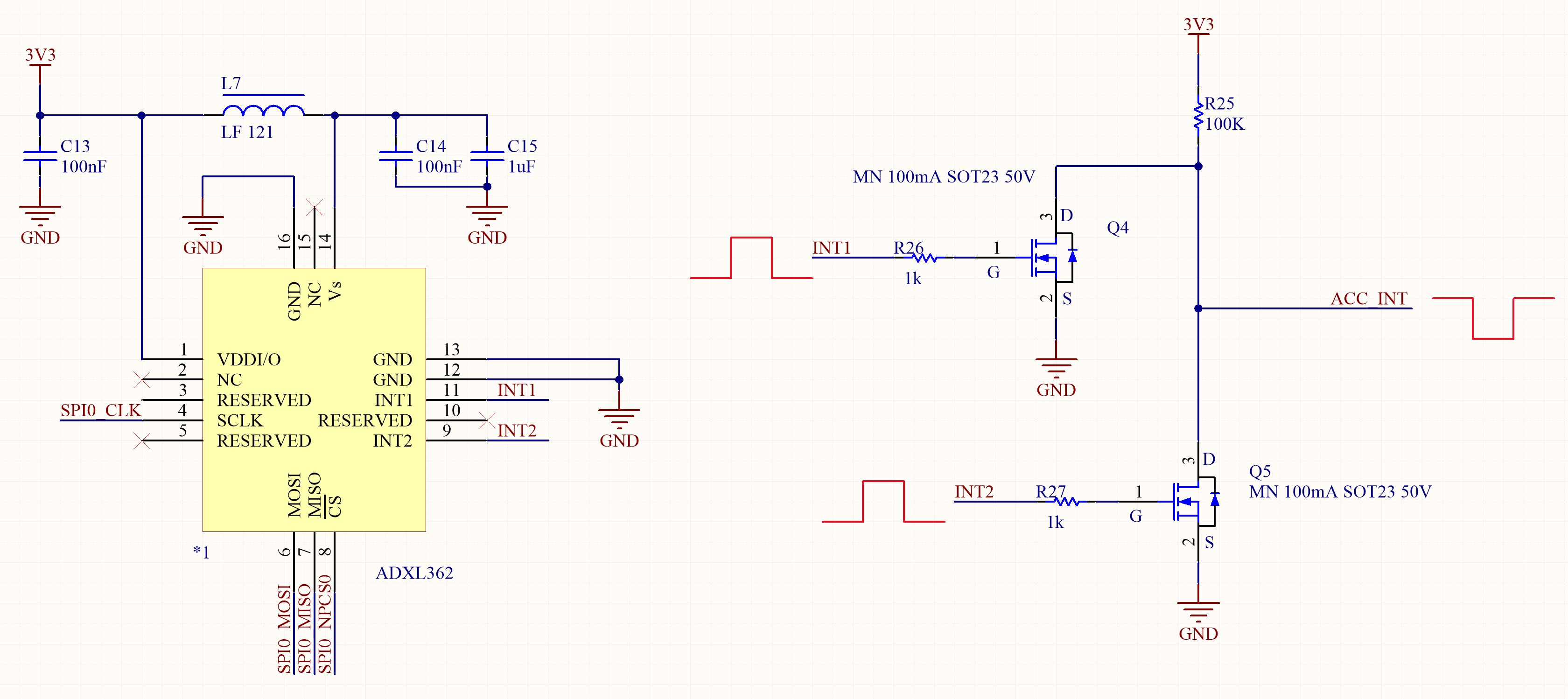
An interrupt on one of the wakeup inputs can be used to resume the system after entering in sleep mode. A possible way to do that is using an accelerometer. This one too can be put in a low power mode and trigger an interrupt when the acceleration rises above a chosen threshold at least on one of the three axes. Moving or tapping the display resumes the system enabling its usage in a short time.
Related links
- Roadrunner pinout schematic
- Roadrunner pinout details
- Documentation page
- SAMA5D2 Series datasheet
- 5" LCD panel with Capacitive Touch Panel
- AP5727 boost converter
- ADXL362 accelerometer
Shopping list
