How to design the USB circuitry
Introduction
USB bus is one of the most widely spread interconection system among computer and a huge number of different devices. This requires to divide in some different classes the different possible configurations. The Roadrunner SOM uses a Microchip SAMA5D27 MCU. As described on SAMA5D2 Series datasheet it can support the following USB connections:
- One USB high-speed device port (UDPHS) and one USB high-speed host port or two USB high-speed host ports (UHPHS)
- One USB high-speed host port with a High-Speed Inter-Chip (HSIC) interface.
As explained in the SAMA5D2 Series datasheet 42.6.3 HSIC
The High-Speed Inter-Chip (HSIC) is a standard for USB chip-to-chip interconnect with a 2-signal (strobe, data) source synchronous serial interface using 240 MHz DDR signaling to provide only high-speed 480 Mbps data rate. External cables, connectors and hot plug & play are not supported. The HSIC interface operates at high speed, 480 Mbps, and is fully compatible with existing USB software stacks. It meets all data transfer needs through a single unified USB software stack.
For this reason here are described only the host and device connections for the USB ports.
More from the SAMA5D27 datasheet:
41. USB High Speed Device Port (UDPHS)
41.1 Description
The USB High Speed Device Port (UDPHS) is compliant with the Universal Serial Bus (USB), rev 2.0 High Speed device specification. Each endpoint can be configured in one of several USB transfer types. It can be associated with one, two or three banks of a Dual-port RAM used to store the current data payload. If two or three banks are used, one DPR bank is read or written by the processor, while the other is read or written by the USB device peripheral. This feature is mandatory for isochronous endpoints.
41.2 Embedded Characteristics
- 1 High-speed Device
- 1 UTMI Transceiver shared between Host and Device
- USB v2.0 High Speed (480 Mbits/s) Compliant
- 16 Endpoints up to 1024 bytes
- Embedded Dual-port RAM for Endpoints
- Suspend/Resume Logic (Command of UTMI)
- Up to Three Memory Banks for Endpoints (Not for Control Endpoint)
- 8 Kbytes of DPRAM
and
42. USB Host High Speed Port (UHPHS)
42.1 Description
The USB Host High Speed Port (UHPHS) interfaces the USB with the host application. It handles Open HCI protocol (Open Host Controller Interface) as well as Enhanced HCI protocol (Enhanced Host Controller Interface).
42.2 Embedded Characteristics
- Compliant with Enhanced HCI Rev 1.0 Specification
- Compliant with USB V2.0 High-speed Specification
- Supports High-speed 480 Mbps
- Compliant with OpenHCI Rev 1.0 Specification
- Compliant with USB V2.0 Full-speed and Low-speed Specification
- Supports both Low-speed 1.5 Mbps and Full-speed 12 Mbps USB devices
- Root Hub Integrated with 3 Downstream USB HS Ports
- Embedded USB Transceivers
- Supports Power Management
- 2 Hosts (A and B) High Speed (EHCI), Port A shared with UDPHS
- 1 Host (C) High Speed only (HSIC)
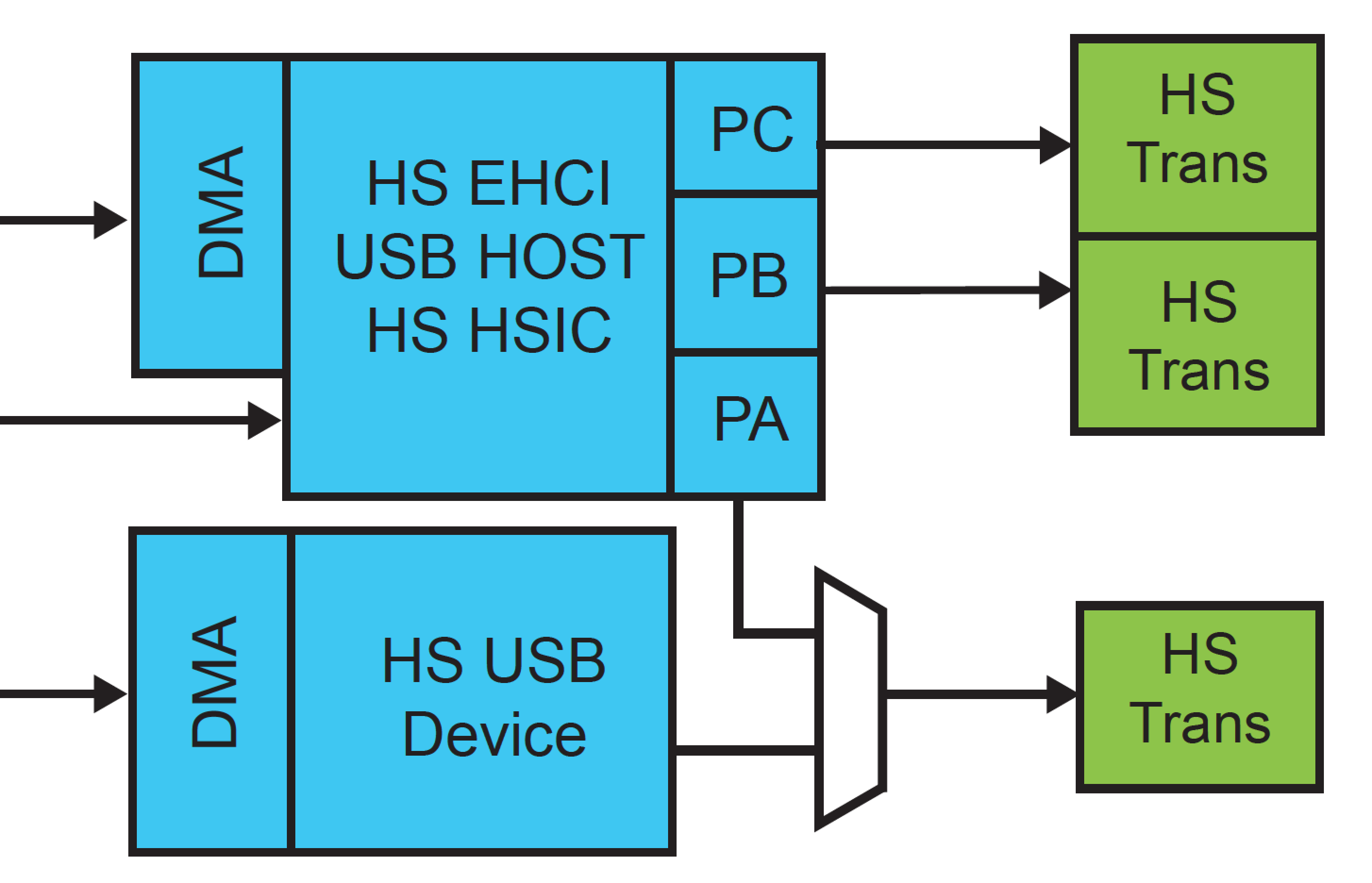
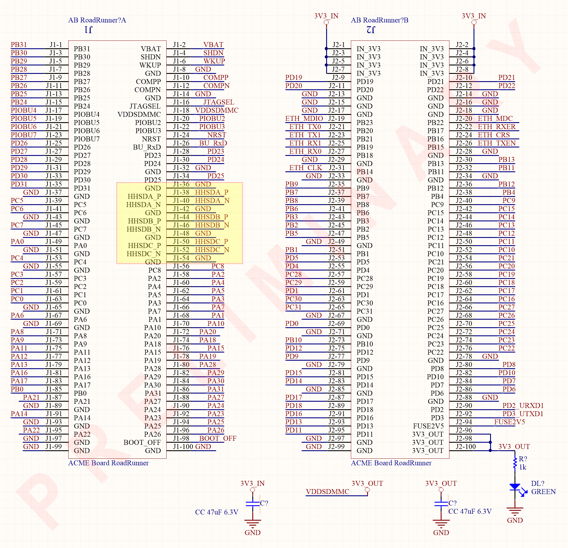
As shown in the picture above, the High Speed USB Host Port A is shared with the High Speed USB Device port. The HHSDPA/HHSDMA port (USB Host Port A High Speed Data) can be used alternatively with the DHSDP/DHSDM (USB Device High Speed Data) on the same pins.
Physical layer
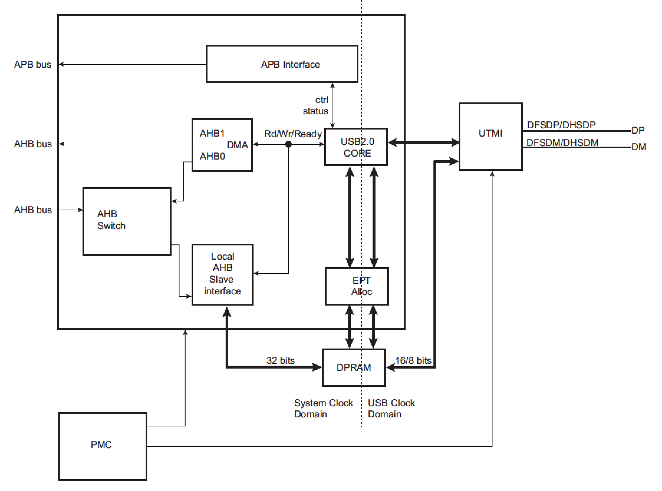
There are standard specifications that define the USB 2.0 Transceiver Macrocell Interface (UTMI) and explores the many operational aspects of the USB 2.0 Transceiver Macrocell (UTM), as well as some of the key features like data serialization, bit stuffing, clock recovery, and more. Due to speed requirements of an USB connection, analog features are required in the design and a PHY layer is being employed. This is made as a hard macro. To make it reusable a standard interface has been defined. So anybody who does a USB design can just do the non-PHY portion compliant to UTMI interface and can buy an off the shelf USB PHY hardmacro and interface with it.
The Roadrunner MCU includes the PHY in the USB peripheral, so it only requires to develop the differential controlled impedance line toward connectors.
ESD and overvoltage protection
Some considerations about ESD catched by long lines can be read on a previous article regarding ethernet
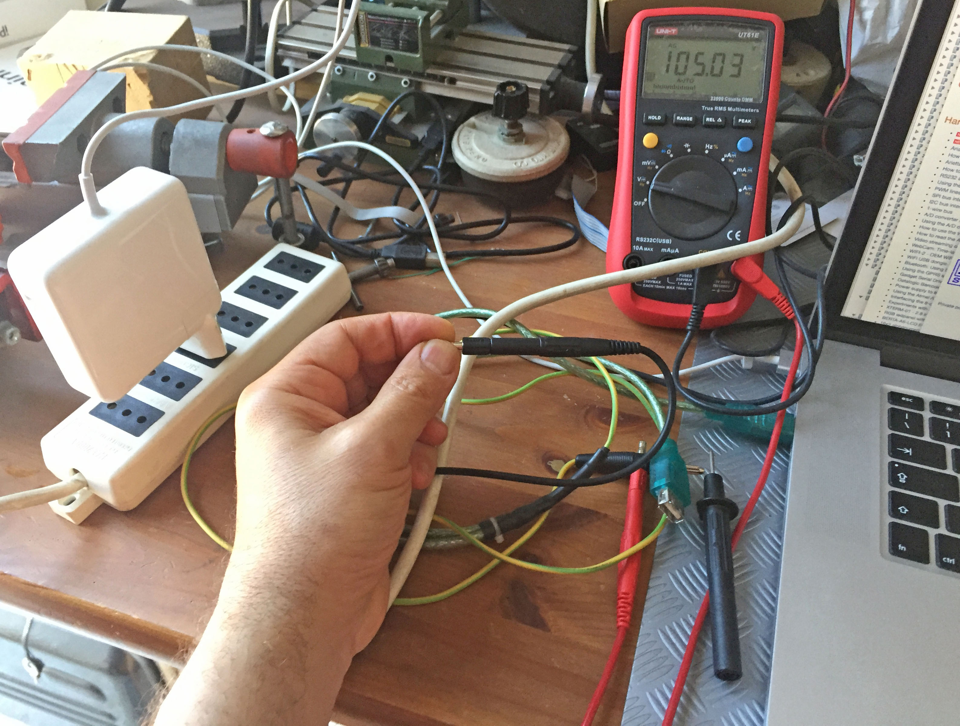
At a first look, it seems that USB, with its limited line length, it's less susceptible to such problems. Due to the very wide range of utilization, instead, many other situations can cause ESD or overvoltage levels dangerous for the electronics components. The most obvious one is the thousands volts ElectroStatic Discharge (ESD) injected to a ground connected device by a human body charged by the friction of insulated clothes and shoes in a very dry environment. Another sneaky configuration to can apply to the MCU peripheral pins a dangerous voltage level. A small wall power supply can be realized (and legally sold) also without an earth connection to the main power line. Using the so called double insulation it's admitted in many environment. Beacause it's cheaper and lighter than standard grounded cables, very often the laptop computers use this kind of two wires supply.
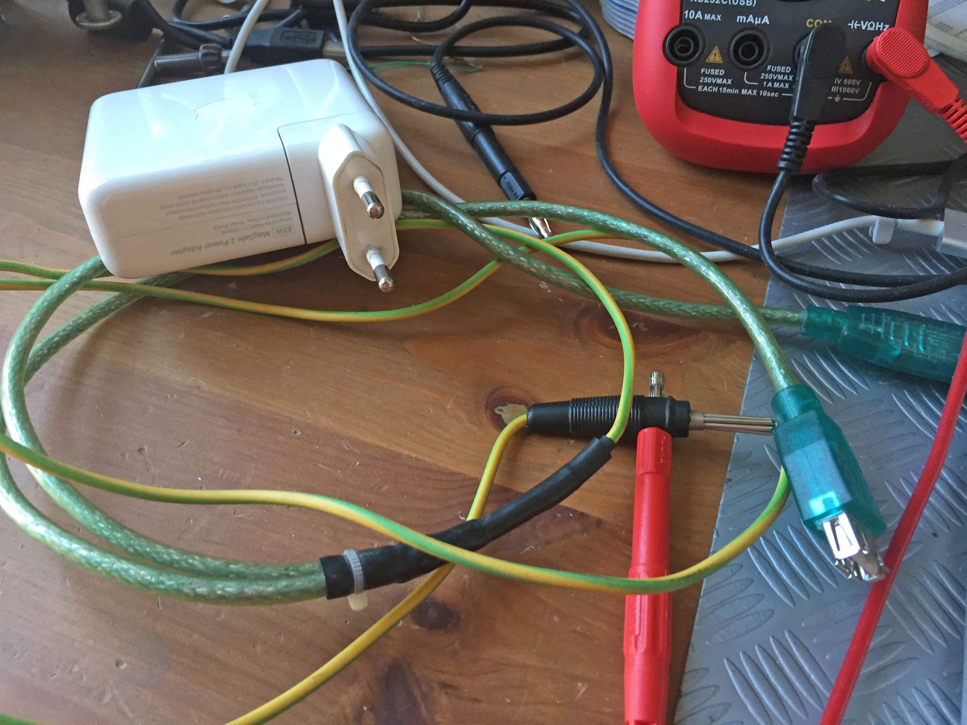
It's very easy to test, please try this at home, the potential difference between the shield of an USB cable and ground. In this picture the body is just in contact with the floor. The voltage is more then 100V. The very low supplied current, due to the filter capacitor leakage, is completely safe (and legal). It's not able at all to injure human body nor to heat wires or electrical components, but the voltage sensitive devices can be damaged by breaking down the junctions or low voltage insulations.
Differential path routing
USB connection uses a differential signals transmission mode. The basic principles and PCB routing suggestions are the same described in the article regarding ethernet and this can be directly applied to USB developing just calculating a differential impedance of 90Ω instead of 100Ω.
Schematic
As abovementioned the USB interface can be used in many different way. Let's summarize the previous considerations for some schematic examples keeping in mind the differences between USBA, USBB and USBC peripherals of the Roadrunner and its pinout
Example 1
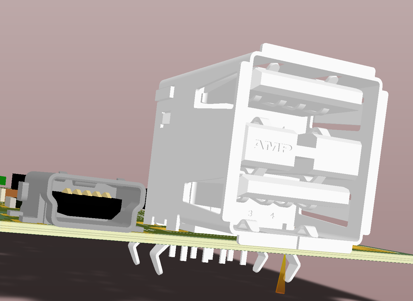
In this example an USB type A vertical socket is used as an host connection and a micro USB just to power up the board.
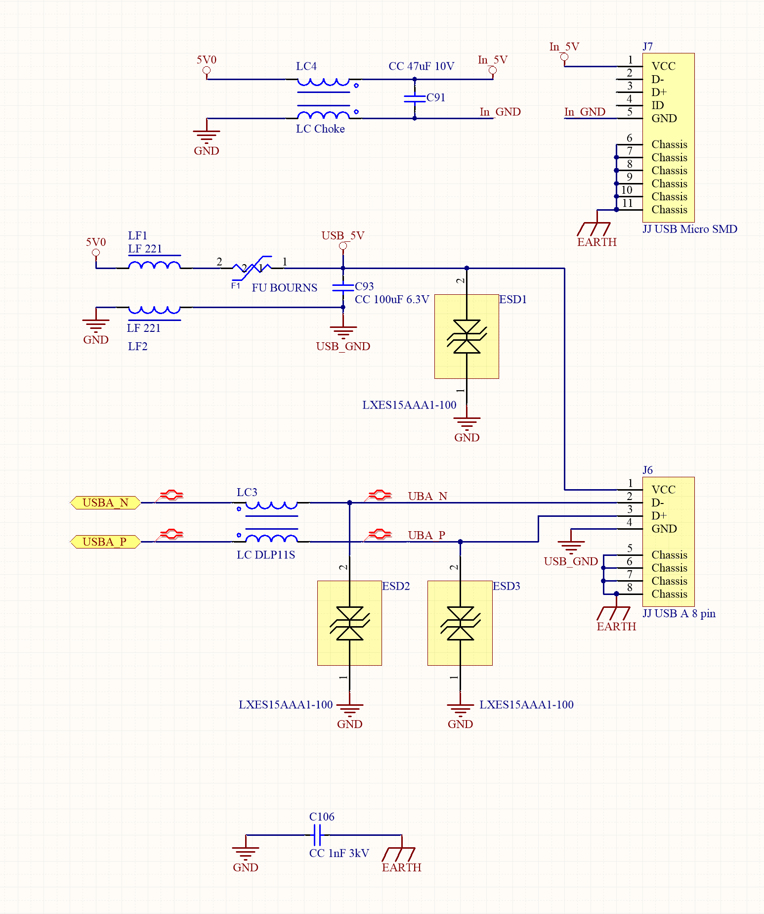
The shield of both the USB jacks are connected on a separated plane, called here EARTH to distinguish it from the general GND plane and insulated from it with at least 1mm gap. The two planes are in contact, from the point of view of the signal, only through a 1nF/3kV capacitor. Each line is protected, from both ESD and overvoltage, by a low capacitance electrostatic discharge protection devices. Common mode noise on the differential lines is rejected by the common mode chokes. An LC lowpass filter is placed on the power lines to filter out high frequency noise both from outside to internal circuit and viceversa, in order to comply the EMC CE specifications. Because the host connector could also power up an external device (e.g.: for external storage) a resettable class='acmetable' fuse protects the internal power supply from overcharching.
Example 2
In this example a double stacked USB type A horizontal socket is used for two host connections and a mini USB for a device connection.
All the contacts are used. Only the noise filtering devices are shown.
Example 3
The USB bus can also be used just to connect an internal device. In this case no ESD protection is required, but all the rules about differential lines must be applied.
Example 4
Another special case. The USB micro connector is used to interface an USB-serial converter to have an external link to the MCU serial console.
PCB
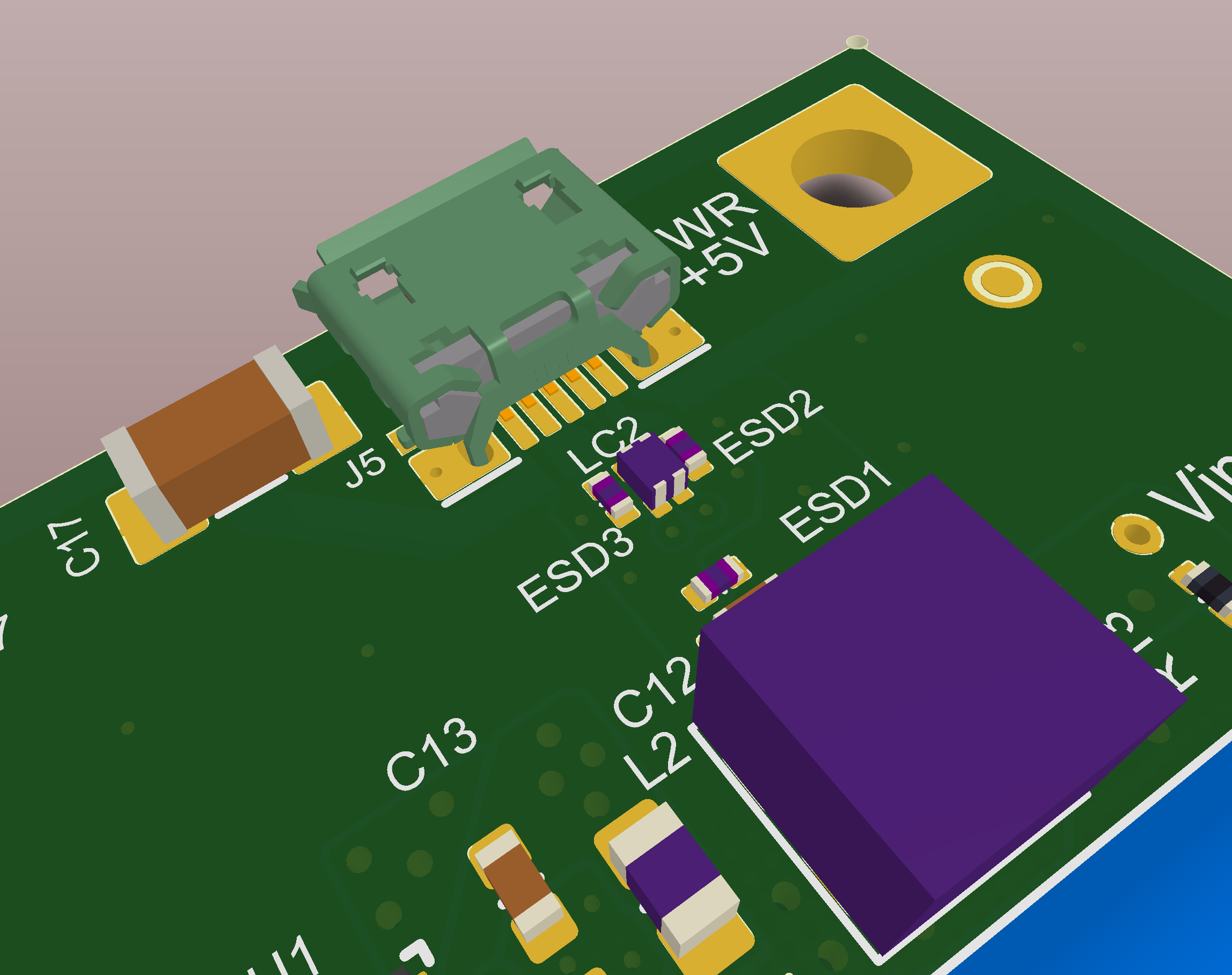
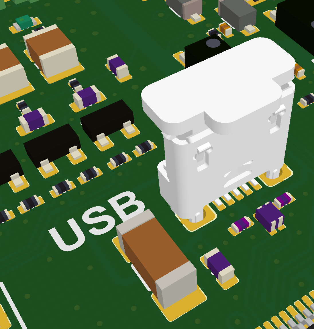
Let's show the PCB routing for the schematic in the example 1 to explain the care to apply on the design.
It's evident the gap from EARTH to GND used to insulate the ESD on the jack shield from the internal circuits and the C106 capacitor to ground them for the high frequency signal, as explained above.
Connector types
In addition to the vertical type A and micro SMD already shown, below there are some other examples of connectors normally used.
In order to improve the robustness for a frequently used micro USB jack we can use an SMD version with PTH pins on the shield.
When there is not enough space or the edges of the PCB are inaccessible, a vertical micro connector can be used.
These are the connectors used for the example 2. Double stacked host type A and a mini B for device.
Related links
