DAISY-10 - RS485/422 optoisolated interface
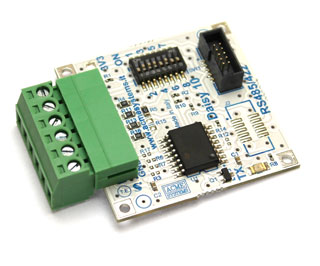
The Daisy-10 is a RS485 half-duplex interface or RS422 full-duplex interface for Terra and Fox boards. It can be configurate ad opto-isolated or not via a set of dip switches. When configured in RS485 mode up to 32 devices are pluggable on a single RS485 bus line.
The board is built around a Texas Instruments ISO35 that provide 2500 Vrms of isolation with the on-field bus line. When isolated an external 3.3VDC power lines is required.
The daisy connectors where it's possible to plug this board are:
| TERRA | FOX G20 | Serial device | Mode available |
|---|---|---|---|
| D13 | D1 | /dev/ttyS2 | RS422 or RS485 |
| D3 | /dev/ttyS1 | RS422 or RS485 | |
| D10 | D6 | /dev/ttyS4 | RS422 or RS485 |
| D8 | /dev/ttyS3 | RS422 |
On the FOX Board G20 is requested a Daisy-1 adapter to wire-up this boards.
Errata corrige
We found a hardware bug when this board is used in isolated mode. Please verify whether the D1 led (3V3) is already removed, if not please remove it. If you are using the board in not isolated mode you can leave it.
RS485 mode
RS485, also known as TIA/EIA-485, is a standard defining the electrical characteristics of drivers and receivers for use in balanced digital multipoint systems. This standard is widely used for communications in industrial automation because it can be used effectively over long distances and in electrically noisy environments.
Even though the data is transmitted over a 2-wire twisted pair bus, all RS485 transceivers interpret the voltage levels of the differential signals with respect to a third common voltage. Without this common reference, a set of transceivers may interpret the differential signals incorrectly.
RS485 dip-switch setup
| Dip-switch # --> | 1 | 2 | 3 | 4 | 5 | 6 | 7 | 8 |
|---|---|---|---|---|---|---|---|---|
| RS485 mode | ON | ON | ON | OFF | ||||
| Isolated | OFF | OFF | ||||||
| Not isolated | ON | ON | ||||||
| A & B terminated | ON | |||||||
| A & B not terminated | OFF | |||||||
| RX disabled on TX | ON | |||||||
| RX always enabled | OFF |
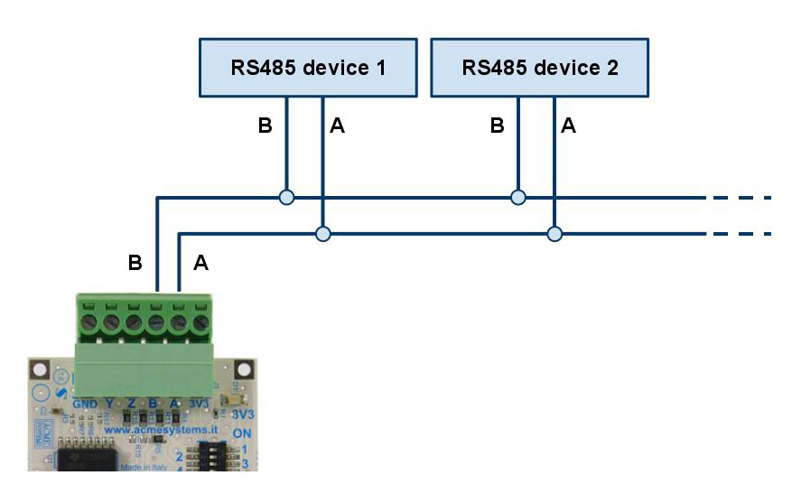
The picture below illustrates a typical RS485 wiring in non isolated mode. In isolated mode you have to provide the 3.3VDC. Don't forget to place a 120 resistor on the last node.
Code example
Following an example of code in Python to use the Daisy-10 module in RS485 mode.
The Daisy-10 class is a derived class from pySerial where it is possible to called the serial ports also with the Daisy connectors name like D1, D10, etc instead of /dev/ttyS2, /dev/ttyS4 etc. Refer to the pySerial doc to learn more about its use:
RS422 mode
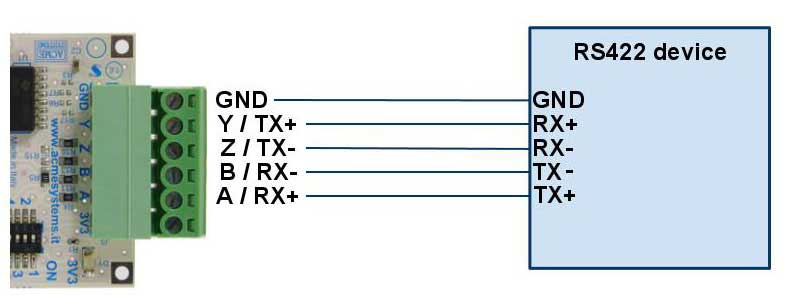
The picture below illustrates a typical RS422 wiring in non isolated mode. In isolated mode you have to provide the 3.3VDC.
RS422 dip-switch setup
| Dip-switch # --> | 1 | 2 | 3 | 4 | 5 | 6 | 7 | 8 |
|---|---|---|---|---|---|---|---|---|
| RS422 mode | OFF | OFF | OFF | OFF | OFF | OFF | ||
| Isolated | OFF | OFF | ||||||
| Not isolated | ON | ON |
Code example
Following an example of code in Python to use the Daisy-10 module in RS422 mode.
The Daisy-10 class is a derived class from pySerial where it is possible to called the serial ports also with the Daisy connectors name like D1, D10, etc instead of /dev/ttyS2, /dev/ttyS4 etc. Refer to the pySerial doc to learn more about its use:
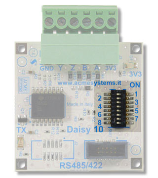
Terminal block pinout
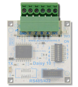
The bus line signals are available on a pluggable terminal block with a pitch of 3.81mm.
| Pin | Signal |
|---|---|
| GND | GND signal when not isolated or external GND line when isolated |
| Y (TX+) | RS422 TX+ line |
| Z (TX-) | RS422 TX- line |
| B (RX-) | RS422 RX+ line or RS485 B line |
| A (RX+) | RS422 RX+ line or RS485 A line |
| 3V3 | 3V3 volt output when not isolated or external 3.3 VDC line when isolated |
Dip-switch set up
Ten dip-switches are available to configure your Daisy-10 interface in RS485 or RS232 mode. This is a list of each dip function. Quick configuration table class='acmetable's are available later in this article.
| Dip-switch # | Function |
|---|---|
| 1 | When ON wires the internal 3.3V to the screw driver terminal. Let it OFF for isolated interfacing |
| 2 | When ON wires A to Y |
| 3 | When ON wires B to Z |
| 4 | When ON wires a 120 resistor between the A and B terminal |
| 5 | When ON wires the internal GND to the screw driver terminal. Let it OFF for isolated interfacing |
| 6 | When ON wires the CPU RTS signal to the DE IC driver |
| 7 | When ON wires DE to RE# on IC driver |
| 8 | When ON wires the CPU CTS signal to the RE# IC driver |
