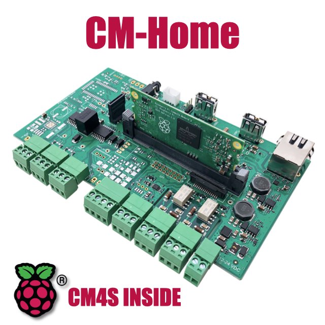
CM Home technical documentation
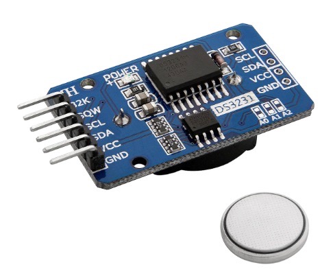
DS3231 I2C Real Time Clock
This article illustrate how to use the Az-Delivery Real Time Clock RTC DS3231 I2C module with the CM-Home
Wirings
These are the signal wirings between the AZ-Delivery Real Time Clock (RTC) DS3231 module and the Grove port on the CM-Home board.
| Home Pin # | Home signal | Az signal |
|---|---|---|
| 1 | SCL (GPIO45) | SCL |
| 2 | SDA (GPIO44) | SDA |
| 3 | 3V3 | VCC |
| 4 | GND | GND |
config.txt
Add these lines to /boot/firmware/config.txt file:
# Set the I2C1 on GPIO 44 and GPIO 45 pins
dtoverlay=i2c1,pins_44_45
dtoverlay=i2c-rtc,ds3231
then reboot the Raspberry Pi.
Check if the kernel has detected the RTC chip:
$dmesg | grep -i rtc
[    2.015759] rtc-ds1307 1-0068: registered as rtc0
[    2.021607] rtc-ds1307 1-0068: setting system clock to 2025-03-24T23:53:18 UTC (1742860398)
Read the time from the RTC chip:
$ sudo hwclock --show
2025-03-25 01:01:36.704186+01:00
Links
- Seeedstudio Grove interface
- Az-Delivery DS3231 eBook
- Az-Delivery DS3231 product page
- https://github.com/raspberrypi/linux/blob/rpi-4.9.y/arch/arm/boot/dts/overlays/README#L783
Products related


All-in-one 7 inch touch POE terminal powered by Raspberry Pi CM4S
- 7 inch TFT display 800x480 pixel
- Capacitive touch
- Embedded micro UPS for safe shutdown
- Power Over Ethernet @ 10/100 Mbit
- Hi-resolution audio up to 384KHz@32bit
- Real Time Clock with backup battery
- 3 USB Host port
- 1 RS485/422/RS232 port
- 1 Relay
- MIPI Camera connector
- WiFi @ 2.4 GHz (optional)