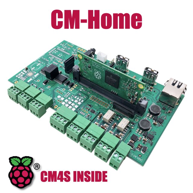
CM Home technical documentation
Pinout and GPIO allocation on CM-Home
GPIO allocation
GPIO 0  - I2C0 - SDA Mipi Camera
GPIO 1  - I2C0 - SCL Mipi Camera
GPIO 2  - IO1  - Mipi Camera
GPIO 3  - IO0  - Mipi Camera

GPIO 4  - unused
GPIO 5  - unused
GPIO 6  - unused

GPIO 7  - SPI CE1
GPIO 8  - SPI CE0
GPIO 9  - SPI MISO
GPIO 10 - SPI MOSI
GPIO 11 - SPI SCLK

GPIO 12 - unused
GPIO 13 - unused

GPIO 14 - unused (Ex TXD0 TP-uart)
GPIO 15 - unused (RXD0 TP-uart)

GPIO 16 - 1-Wire port

GPIO 17 - unused
GPIO 18 - Display backlight (1=On)
GPIO 19 - unused
GPIO 20 - IR receiver port

GPIO 21 - Left relay
GPIO 22 - Right relay

GPIO 23 - Display RST
GPIO 24 - Display D/C
GPIO 25 - Display IRQ
GPIO 26 - Available GPIO on J3
GPIO 27 - Available GPIO on J3

GPIO 28 - Left Input dry contact (1)
GPIO 29 - Right Input dry contact (2)

GPIO 30 - unused (Ex Light bus Rx)
GPIO 31 - unused (Ex Light bus Tx)

GPIO 32 - TXD1 Debug port
GPIO 33 - RXD1 Debug port

GPIO 34 - RGB led - Blue  - (0=On)
GPIO 35 - RGB led - Green - (0=On)
GPIO 36 - RGB led - Red   - (0=On)

GPIO 37 - WiFi power-on (1=ON)

GPIO 38 - unused (Ex Yarm reset)
GPIO 39 - unused (Ex Yarm)

GPIO 40 - PWM0 OUT - Audio left channel
GPIO 41 - PWM1 OUT - Audio right channel
GPIO 42 - unused
GPIO 43 - unused

GPIO 44 - I2C1 SDA Groove port #1
GPIO 45 - I2C1 SCL Groove port #1
J3 (SPI) Pinout
Come si può fare per estrarre da youtube una lista jsn 1 - 3V3 out
2 - 3V3 out
3 - SPI0 CE1 - GPIO 7
4 - Display backlight - GPIO 18 - (1=On)
5 - SPI0 CE0 - GPIO 8
6 - Display reset - GPIO 23
7 - SPI0 MOSI - GPIO 10
8 - Display D/C - GPIO 24
9 - SPI0 MISO - GPIO 9
10 - Display IRQ - GPIO 25
11 - Available - GPIO 26
12 - Available - GPIO 27
13 - GND
14 - SPI0 SCLK - GPIO 11
15 - GND
16 - GND
Serial port allocation
/dev/ttyUSB0 - Left RS485 port
/dev/ttyUSB1 - Yarm serial link
/dev/ttyUSB2 - Right RS485 port
/dev/ttyUSB3 - Serial port interface
/dev/ttyAMA0 - TP-Bus
/dev/ttyS0   - Debug port
Products related
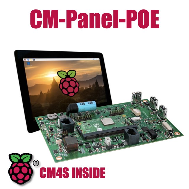
All-in-one 7 inch touch POE terminal powered by Raspberry Pi CM4S
- 7 inch TFT display 800x480 pixel
- Capacitive touch
- Embedded micro UPS for safe shutdown
- Power Over Ethernet @ 10/100 Mbit
- Hi-resolution audio up to 384KHz@32bit
- Real Time Clock with backup battery
- 3 USB Host port
- 1 RS485/422/RS232 port
- 1 Relay
- MIPI Camera connector
- WiFi @ 2.4 GHz (optional)