CM Panel technical documentation
Raspberry Pi OS for CM-Panel BASIC
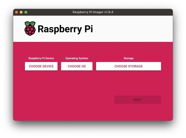
Download and install on your PC the Raspberry Pi Imager from this url:
then launch it.
In this point, you can choose whether to use a ready-to-use image from those available on this page Download binary images for CM Panel or to modify the standard image downloaded from the Raspberry site. The ready-to-use images have nevertheless been derived from the standard distributions with some modifications to enable the TFT display and touch instead of the HDMI output.
Continue using the official Raspberry image
If on your CM-Panel is mounted a Raspberry CM4S module press the CHOOSE DEVICE button and select Raspberry Pi 4
Press the CHOOSE OS button and select the Raspberry Pi OS you like. In this
example we will use Raspberry Pi OS (other) -> Raspberry Pi OS Lite (64-bit)
Insert in your PC the blank microSD and press the CHOOSE STORAGE button and select
the microSD storage.
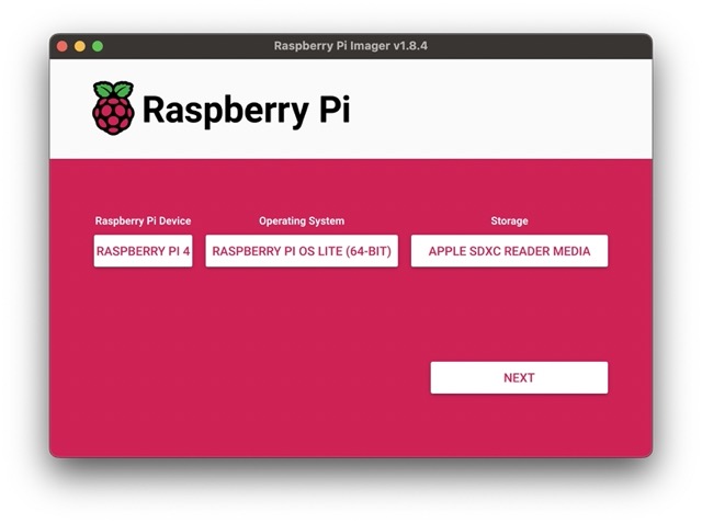
Press the NEXT button.
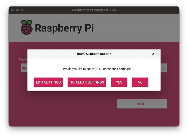
Press the EDIT SETTINGS button.
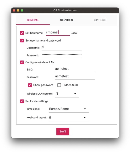
In this form set the hostname of your CM Panel, the user and password.
If you are using a CM Panel BASIC WIFI insert the name of your WiFi (SSID) and the password to get the access.
Switch to the tab SETTINGS and enable the SSH access.
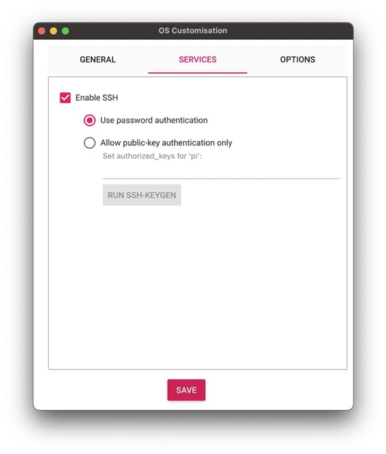
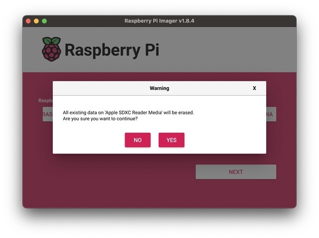
Press the SAVE button the the YES button.
The YES again.
After the writing and verifying operation, remove the microSD card and insert it again to see the content of the first microSD partition
called bootfs the make these changes on the stardard files present on this partition.
Changes on config.txt file
Open the file config.txt with a text editor and change its content with this:
# For more options and information see
# http://rptl.io/configtxt

#Ignore the HDMI cable hotplug (to avoid the delay at startup)
hdmi_ignore_hotplug=1

# Set the debug port on GPIO32, GPIO33 pins
force_turbo=1
dtoverlay=uart1,txd1_pin=32,rxd1_pin=33

# Automatically load initramfs files, if found
auto_initramfs=1

# Enable DRM VC4 V3D driver
dtoverlay=vc4-kms-v3d
dtoverlay=vc4-kms-dpi-generic
max_framebuffers=2

# Run in 64-bit mode
arm_64bit=1

# Disable compensation for displays with overscan
disable_overscan=1

# Run as fast as firmware / board allows
arm_boost=1

# Set I2C port on the pin wired to the touch controller
dtoverlay=i2c1,pins_44_45
dtoverlay=goodix-7-acme

## Enable the DPI port to talk with the TFT display
dtoverlay=dpi18
overscan_left=0
overscan_right=0
overscan_top=0
overscan_bottom=0
framebuffer_width=800
framebuffer_height=480
enable_dpi_lcd=1
display_default_lcd=1
dpi_group=2
dpi_mode=87
dpi_output_format=0x6f005
hdmi_timings=800 0 40 48 88 480 0 13 3 32 0 0 0 60 0 32000000 6
Changes on cmdline.txt file
Open cmdline.txt and change this line:
console=serial0,115200
in:
console=serial1,115200
In this way the serial console messages will be transmitted on the DEBUG_TX and DEBUG_RX lines available on the EXP2 connector.
Add goodix-7-acme.dtbo overlay blog file
Goodix is the brand of I2C chip mounted to the touchscreen. The file
goodix-7-acme.dtbo is used to enable the Goodix I2C Linux driver and use the rigth
lines and I2C address.
Download and save goodix-7-acme.dtbo in the overlays directory:
If your like to check the device tree source used to generate this file click on this link:
To generate the .dtbo file from thr .dts source use this command:
sudo dtc -@ -I dts -O dtb -o /boot/overlays/goodix-7-acme.dtbo /boot/overlays/goodix-7-acme.dts
Add the dt-blob.bin blog file
The file dt-blob.bin defines the lines used by the Raspberry camera for the I2C bus on the CM-Panel.
Download and save it in the boot directory:
of your prefere you can compile it from this source:
To compile it you need a Linux PC or a Raspberry Pi and a Device Tree Compiler:
sudo dtc -I dts -O dtb -o /boot/dt-blob.bin /boot/dt-blob.dts
Bootstrap
Umount the microSD from your PC and boot it on your CM-Panel
Links
Products related
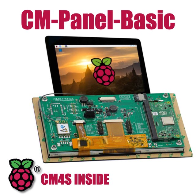
- 7 inch TFT display 800x480 pixel
- Capacitive touch
- Embedded micro UPS for safe shutdown
- Power Over Ethernet @ 10/100 Mbit
- Hi-resolution audio up to 384KHz@32bit
- Real Time Clock with backup battery
- 3 USB Host port
- 1 RS485/422/RS232 port
- 1 Relay
- MIPI Camera connector
- WiFi @ 2.4 GHz (optional)