Roadrunner technical documentation
Using the MMC0 bus instead of MMC1 on roadrunner
This article illustrates how to boot and run Linux from a microSD card wired on MMC0 bus instead on MMC1
Wirings
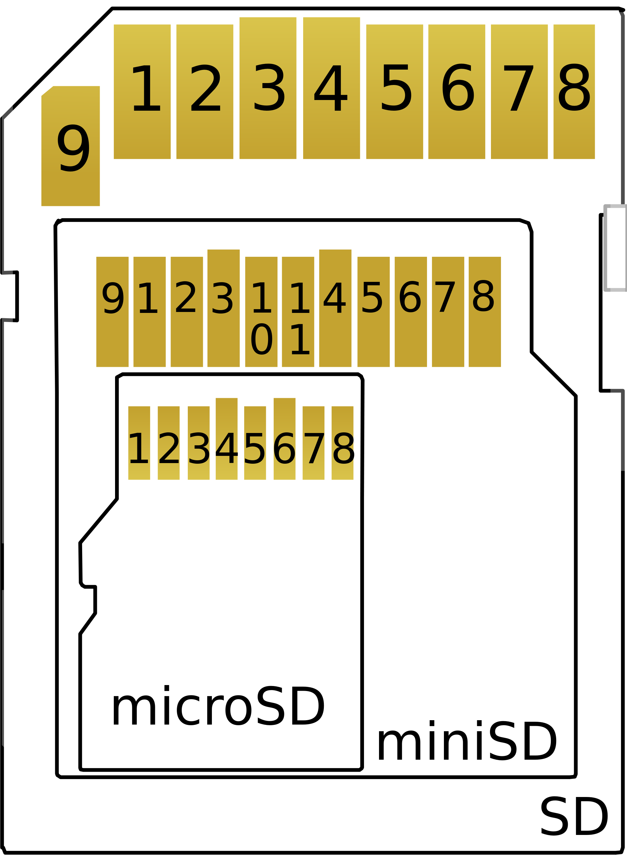
There are the wirings between the Roadrunner module and a microSD/miniSD or SD card
| CPU lines | SD signals | SD pin | uSD pin |
|---|---|---|---|
| PA0 | CLK | 5 | 5 |
| PA1 | CMD | 2 | 3 |
| PA2 | DATA 0 | 7 | 7 |
| PA3 | DATA 1 | 8 | 8 |
| PA4 | DATA 2 | 9 | 1 |
| PA5 | DATA 3 | 1 | 2 |
| VCC | 4 | 4 | |
| GND | 3,6 | 6 | |
| PA13 (*) | CD |
(*) The PA13 line must be wired on CD (Carrier detect) line if your microSD socket has this pin or fixed on GND if not.
A 68 kOhm pull-up resistor must be wired on each of these lines:
- DATA 0
- DATA 1
- DATA 2
- DATA 3
- CMD
Device tree binding
This is the device tree definition to use:
ahb {

    ...

    sdmmc0: sdio-host@a0000000 {
        bus-width = <4>;
        pinctrl-names = "default";
        no-1-8-v;
        non-removable;
        pinctrl-0 = <&pinctrl_sdmmc0_default>;
        status = "okay";
    };

    sdmmc1: sdio-host@b0000000 {
        bus-width = <4>;
        pinctrl-names = "default";
        pinctrl-0 = <&pinctrl_sdmmc1_default>;
    };

    ...


    apb {

        ...

        pinctrl_sdmmc0_default: sdmmc0_default {
            cmd_data {
                pinmux = <PIN_PA1__SDMMC0_CMD>,
                     <PIN_PA2__SDMMC0_DAT0>,
                     <PIN_PA3__SDMMC0_DAT1>,
                     <PIN_PA4__SDMMC0_DAT2>,
                     <PIN_PA5__SDMMC0_DAT3>;
                bias-disable;
            };

            ck_cd_rstn_vddsel {
                pinmux = <PIN_PA0__SDMMC0_CK>,
                     <PIN_PA13__SDMMC0_CD>;
                bias-disable;
            };
        };

        ...


    };

    ...


};
at91bootstrap config
To be compatible with boot from MMC0, at91bootstrap must be compiled with these flags configured inside the make menuconfig command (read Compiling AT91bootstrap 3.9.1)
Memory selection  --->
  Flash Memory Technology (SD card)  --->
    ( ) Dataflash
    (X) SD card
and
Memory selection  --->
    SD Card Configuration  --->
        SD Host Controller Select (On SDHC0)  --->
            (X) On SDHC0
            ( ) On SDHC1
Related products
Low-power Linux System On Module
- CPU Microchip SAMA5D27
- Cortex A5 @ 500 MHz
- Low power consumption:
Suspend to RAM mode 10mW
Full speed: 396mW - Debian, Buildroot and Yocto Linux
- Fully open source drivers

Single Board Computer based on RoadRunner Linux SOM (Included)
- Low power consumption
- Two USB Host 2.0 ports (one configurable as USB client on the USB-C connector)
- One 10/100 Mbit/s Lan port
- 2 Acme Sensor ports
- Huge set of GPIOS, SPI, I2C and serial lines
Evaluation board for RoadRunner SOM
- All the circuitries you need to test the RoadRunner SOM
- USB host, USB device, Ethernet port, MicroSD socket
- Test points for power consumption measurements
- All the Roadrunner signals exposed on 2.54mm pitch pins
- On-board supercap for RTC and backup memory circuit
