Roadrunner technical documentation Buy
How to use the SPI ports
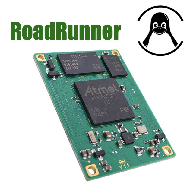
This article illustrates how to use the SPI ports on Acme Systems Road Runner SOM based on Microchip
SAMA5D27 MPU
Pinout of SPI ports
The SPI bus lines are located on the following pins:
| Signal     | Per A | Per B | Per C | Per D | Per E | Per F
|------------|-------|-------|-------|-------|-------|-------
| SPI0 MOSI  | PA15  |       | PB0   |       |       |
| SPI0 MISO  | PA16  |       | PA31  |       |       |
| SPI0 SCLK  | PA14  |       | PB1   |       |       |
| SPI0 CS0   | PA17  |       | PA30  |       |       |
| SPI0 CS1   | PA18  |       | PA29  |       |       |
| SPI0 CS2   | PA19  |       | PA27  |       |       |
| SPI0 CS3   | PA20  |       | PA28  |       |       |
!------------|-------|-------|-------|-------|-------|-------
| SPI1 MOSI  | PD26  |       |       | PC2   | PA23  |
| SPI1 MISO  | PD27  |       |       | PC3   | PA24  |
| SPI1 SCLK  | PD25  |       |       | PC1   | PA25  |
| SPI1 CS0   | PD28  |       |       | PC4   | PA22  |
| SPI1 CS1   | PD29  |       |       | PC5   | PA26  |
| SPI1 CS2   | PD30  |       |       | PC6   | PA27  |
| SPI1 CS3   |       |       |       | PC7   | PA28  |
|------------|-------|-------|-------|-------|-------|-------
Kernel configuration
Device Drivers  --->
  [*] SPI support  --->
    <*>   Atmel SPI Controller
    <*>   User mode SPI device driver support
Device tree
/****************/
/* Enable SPI 0 */
/****************/

spi0: spi@f8000000 {
    pinctrl-names = "default";
    pinctrl-0 = <&pinctrl_spi0_default>;
    status = "okay";

    spidev@0 {
       compatible = "linux,spidev";
       spi-max-frequency = <10000000>;
       reg = <0>;
    };
};

/* Pin definition Peripheral A */

pinctrl_spi0_default: spi0_default {
    pinmux = <PIN_PA14__SPI0_SPCK>,
            <PIN_PA15__SPI0_MOSI>,
            <PIN_PA16__SPI0_MISO>,
            <PIN_PA17__SPI0_NPCS0>,
            <PIN_PA18__SPI0_NPCS1>,
            <PIN_PA19__SPI0_NPCS2>,
            <PIN_PA20__SPI0_NPCS3>;
    bias-disable;
};

/****************/
/* Enable SPI 1 */
/****************/

spi1: spi@fc000000 {
    pinctrl-names = "default";
    pinctrl-0 = <&pinctrl_spi1_default>;
    status = "okay";

    spidev@0 {
       compatible = "linux,spidev";
       spi-max-frequency = <10000000>;
       reg = <0>;
    };

};

/* Pin definition Peripheral D */

pinctrl_spi1_default: spi1_default {
    pinmux = <PIN_PC1__SPI1_SPCK>,
    <PIN_PC2__SPI1_MOSI>,
    <PIN_PC3__SPI1_MISO>,
    <PIN_PC4__SPI1_NPCS0>;
    bias-disable;
};
Links
- Microchip SAMA5D2 Series datasheet
- Use 2.8 inch TFT displays on SPI ports
- Overview of Linux kernel SPI support
- Intro to the userspace API for spi devices
- Example of Device Tree
Related products

Low-power Linux System On Module
- CPU Microchip SAMA5D27
- Cortex A5 @ 500 MHz
- Low power consumption:
Suspend to RAM mode 10mW
Full speed: 396mW - Debian, Buildroot and Yocto Linux
- Fully open source drivers

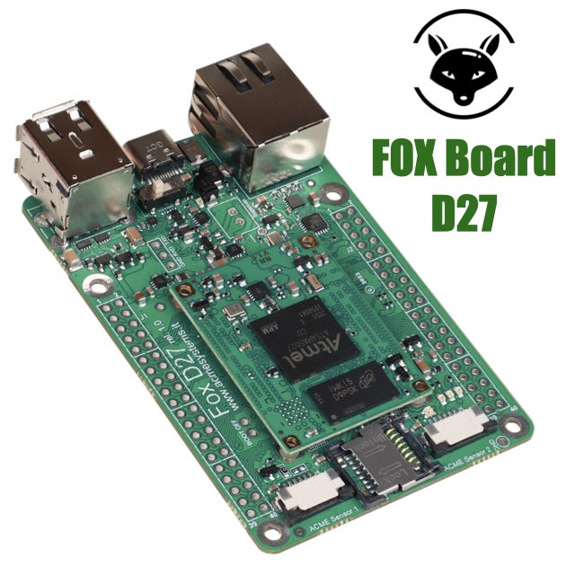
Single Board Computer based on RoadRunner Linux SOM (Included)
- Low power consumption
- Two USB Host 2.0 ports (one configurable as USB client on the USB-C connector)
- One 10/100 Mbit/s Lan port
- 2 Acme Sensor ports
- Huge set of GPIOS, SPI, I2C and serial lines


