Roadrunner technical documentation
Use 2.8 inch TFT displays on SPI ports
Unfortunately on SAMD2 architecture is not available the driver to manage the resistive touch available on XTERM-01
- Kernel used: 4.19.78
- Rootfs used: Buildroot 2020.02
Kernel menuconfig
Enable the kernel SPI drivers as explained here:
Enable the Kernel support for small TFT LCD with ILI9341 LCD Controller
Device Drivers  --->
  [*] Staging drivers  --->
    <*>   Support for small TFT LCD display modules  --->
            <*>   FB driver for the ILI9341 LCD Controller
Example 1: One display on each SPI
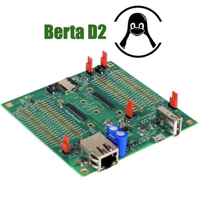
In this example we will use our XTERM-01 wired to Berta Board D2 evaluation kit using the port SPI0 and SPI1 lines (MOSI, MISO, CLK and CS) plus some extra signals required by the display (reset and data/command).
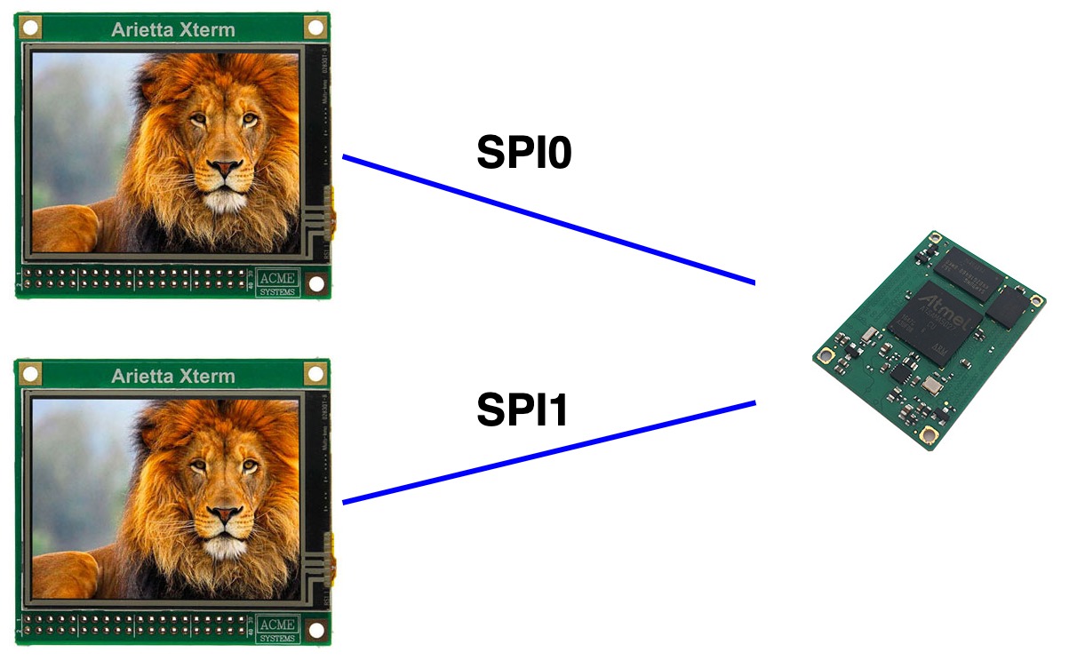
FIRST DISPLAY ON SPI0                   SECOND DISPLAY

| Signal     | Berta D2 | XTerm 0 |   | Signal     | Berta D2 | XTerm 1 |
|------------|----------|---------|   |------------|----------|---------|
| SPI0 MOSI  | PA15     | J4.8    |   | SPI1 MOSI  | PC2      | J4.8    |
| SPI0 MISO  | PA16     | J4.10   |   | SPI1 MISO  | PC3      | J4.10   |
| SPI0 SCLK  | PA14     |  J4.7   |   | SPI1 SCLK  | PC1      | J4.7    |
| SPI0 CS0   | PA17     | J4.25   |   | SPI1 CS0   | PC4      | J4.25   |
|            |          |         |   |            |          |         |
| Reset      | PA13     | J4.33   |   | Reset      | PC5      | J4.33   |
| D/C        | PA12     | J4.31   |   | D/C        | PC6      | J4.31   |
|            |          |         |   |            |          |         |
| 3V3        | 3V3      |  J4.5   |   | 3V3        | 3V3      | J4.5    |
| GND        | GND      |  J4.9   |   | GND        | GND      | J4.9    |
!------------|----------|---------|   |------------|----------|---------|
Device tree definition
/* Enable the SPI port 0 for a display selected by CS0 signal */

spi0: spi@f8000000 {
    pinctrl-names = "default";
    pinctrl-0 = <&pinctrl_spi0_default>;
    status = "okay";

    device@0 {
        rotate = <90>;
        bgr;
        fps = <30>;
        compatible = "ilitek,ili9341";
        spi-max-frequency = <50000000>;
        reg = <0>;
        regwidth = <8>;
        buswidth = <8>;
        verbose = <3>;
        reset-gpios = <&pioA PIN_PA13 0>;
        dc-gpios = <&pioA PIN_PA12 0>;
    };
};


/* Enable the SPI port 1 for a display selected by CS0 signal */

spi1: spi@fc000000 {
    pinctrl-names = "default";
    pinctrl-0 = <&pinctrl_spi1_default>;
    status = "okay";

    device@0 {
        rotate = <90>;
        bgr;
        fps = <30>;
        compatible = "ilitek,ili9341";
        spi-max-frequency = <50000000>;
        reg = <0>;
        regwidth = <8>;
        buswidth = <8>;
        verbose = <3>;
        reset-gpios = <&pioA PIN_PC5 0>;
        dc-gpios = <&pioA PIN_PC6 0>;
    };
};
Example 2: Two displays on the same each SPI
In this example we will use our XTERM-01 wired to Berta Board D2 evaluation kit using the port SPI1 lines (MOSI, MISO, CLK, CS0 and CS1) plus some extra signals required by the display (reset and data/command).
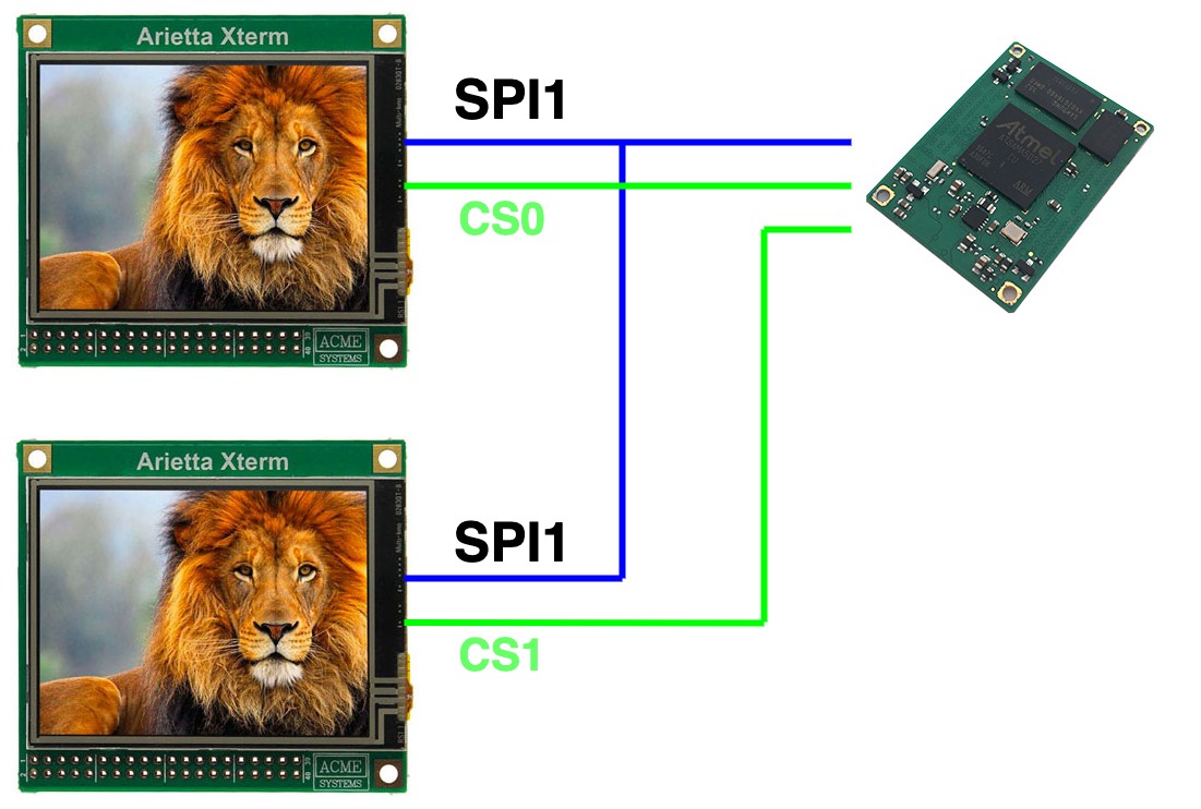
The CS0 and CS1 signals will be used to select the display
| Signal     | Berta D2 | XTerm 0 | XTerm 1 |
|------------|----------|---------|---------|
| SPI1 MOSI  | PC2      | J4.8    | J4.8    |
| SPI1 MISO  | PC3      | J4.10   | J4.10   |
| SPI1 SCLK  | PC1      | J4.7    | J4.7    |
|            |          |         |         |
| SPI1 CS0   | PC4      | J4.25   |         |
| Reset  0   | PA13     | J4.33   |         |
| D/C    0   | PA12     | J4.31   |         |
|            |          |         |         |
| SPI1 CS1   | PC5      |         | J4.25   |
| Reset  1   | PA11     |         | J4.33   |
| D/C    1   | PA8      |         | J4.31   |
|            |          |         |         |
| 3V3        | 3V3      | J4.5    | J4.5    |
| GND        | GND      | J4.9    | J4.9    |
!------------|----------|---------|---------|
Device tree definition
/* Enable the SPI port 1 */

spi1: spi@fc000000 {
    pinctrl-names = "default";
    pinctrl-0 = <&pinctrl_spi1_default>;
    status = "okay";

    /* Display 0 selected by CS0 */

    device@0 {
        rotate = <90>;
        bgr;
        fps = <30>;
        compatible = "ilitek,ili9341";
        spi-max-frequency = <50000000>;
        reg = <0>;
        regwidth = <8>;
        buswidth = <8>;
        verbose = <3>;
        reset-gpios = <&pioA PIN_PA13 0>;
        dc-gpios = <&pioA PIN_PA12 0>;
    };

    /* Display 0 selected by CS1 */

    device@1 {
        rotate = <90>;
        bgr;
        fps = <30>;
        compatible = "ilitek,ili9341";
        spi-max-frequency = <50000000>;
        reg = <1>;
        regwidth = <8>;
        buswidth = <8>;
        verbose = <3>;
        reset-gpios = <&pioA PIN_PA11 0>;
        dc-gpios = <&pioA PIN_PA8 0>;
    };
};
Frame buffer
The display will be managed by Linux using these two devices:
/dev/fb0
/dev/fb1
It will be initializated at startup.
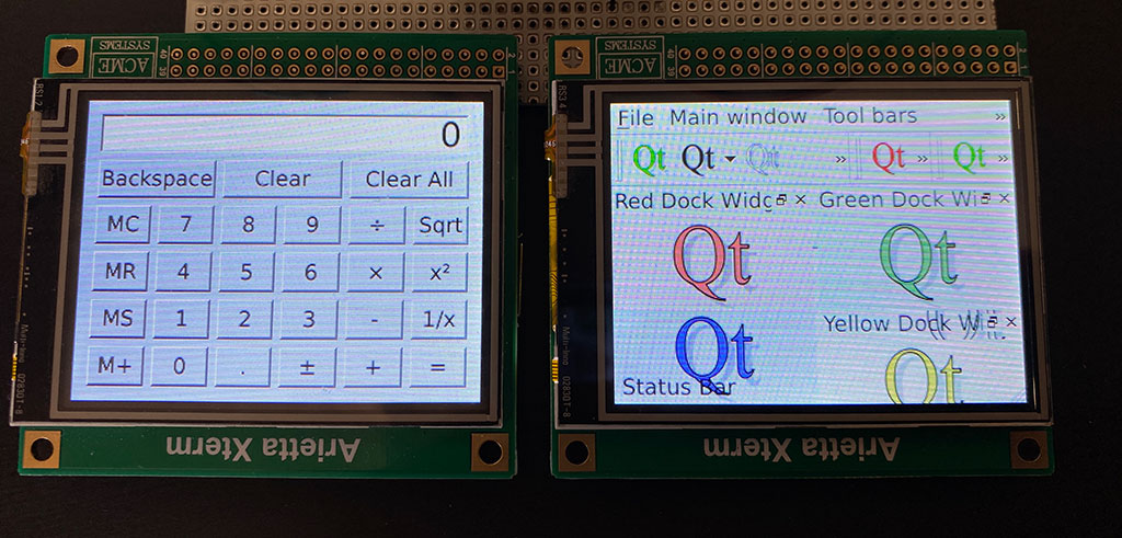
Using QT5
The QT5 applications can select on which display send the output in this form:
/usr/lib/qt/examples/widgets/widgets/calculator/calculator -platform linuxfb:fb=/dev/fb0
/usr/lib/qt/examples/widgets/widgets/calculator/calculator -platform linuxfb:fb=/dev/fb1
Links
- How to use the SPI ports
- Linux Framebuffer drivers for small TFT LCD display modules
- XTERM-01 - 2.8 inch TFT display with resistive touch for Arietta G25
- XTERM-01 Schematic
- IC ILI9341 datasheet
- Build a QT5 application on Buildroot
Related products
- CPU Microchip SAMA5D27
- Cortex A5 @ 500 MHz
- Low power consumption:
Suspend to RAM mode 10mW
Full speed: 396mW - Debian, Buildroot and Yocto Linux
- Fully open source drivers

- Low power consumption
- Two USB Host 2.0 ports (one configurable as USB client on the USB-C connector)
- One 10/100 Mbit/s Lan port
- 2 Acme Sensor ports
- Huge set of GPIOS, SPI, I2C and serial lines
- All the circuitries you need to test the RoadRunner SOM
- USB host, USB device, Ethernet port, MicroSD socket
- Test points for power consumption measurements
- All the Roadrunner signals exposed on 2.54mm pitch pins
- On-board supercap for RTC and backup memory circuit
